
• The move to the new server is done. There are some software and database maintenance updates in process. This has us passing the hat around to help out. We appreciate any donations. Seriously, even a dollar helps. The payment page may be found here - https://www.audiokarma.org/support.html

Yamaha CR-600 restoration advice

Further discrepancies between the schematic and the PCB layout. R705 and R706 are mislabeled in the schematic, R706 should be R705 and Vice versa:
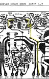
46BD5D2A-E701-4FF0-8E16-62BD426723DC.jpeg

+BL supply goes through R714 and ‘R705’, not R706, and then to VR701. Likewise, anode of D702 is connected to VR702 through ‘R706’, not R705. May not help the issue here much but makes it easier to investigate.

Also I think another connection was not shown which I’ve added below with a dark gray dot on the left below. Both D701 and D702 are 12V 0.5W Zeners with bias currents of 5mA.
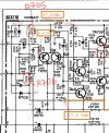
2C63E4C7-2306-477F-9BED-0024AEFF0FFB.jpeg


I don’t trust this schematic as far as I can throw it.
 
Further discrepancies between the schematic and the PCB layout. R705 and R706 are mislabeled in the schematic, R706 should be R705 and Vice versa:

View attachment 3809971

+BL supply goes through R714 and ‘R705’, not R706, and then to VR701. Likewise, anode of D702 is connected to VR702 through ‘R706’, not R705. May not help the issue here much but makes it easier to investigate.

Also I think another connection was not shown which I’ve added below with a dark gray dot on the left below. Both D701 and D702 are 12V 0.5W Zeners with bias currents of 5mA.

View attachment 3809972


I don’t trust this schematic as far as I can throw it.
Thank you very much for all of this. I had noticed some discrepancies with R705/R706, as well as both left channel outputs being flipped on the diagram and the schematic (TR715 sitting on +BL on the diagram, -BL on the schematic, vice versa for TR713). My rudimentary understanding is that to "separate" grounded and ungrounded sections of a trace, you need a capacitor across it. My question is, looking at R704 and R703 they feed directly into R706 and R705 and then onto the + and - BL rails. Where does the ground separation happen? If it's in the trim pots, I can understand it with VR701 as it sits between the ground plane and +BL, however the ground seems to just carry straight across R704 and then down to -BL without anything to really stop it.
 
My rudimentary understanding is that to "separate" grounded and ungrounded sections of a trace, you need a capacitor across it.
I don’t think I understand what is being said here. A capacitor primarily stores up electric charge, voltage across it
cannot change instantaneously, blocks dc current, can be considered an ac short depending on frequency, etc. etc..
however the ground seems to just carry straight across R704 and then down to -BL without anything to really stop it.
??? Not sure I follow.
 
I don’t think I understand what is being said here. A capacitor primarily stores up electric charge, voltage across it
cannot change instantaneously, blocks dc current, can be considered an ac short depending on frequency, etc. etc..

??? Not sure I follow.
Sorry, I think I'm thinking about decoupling capacitors, like C724 and C723 on the amp diagram for example. I guess I'm just very confused as to how, with the way the circuit is set up, there's any way in which I wouldn't have a ground short on the left channel rails, especially -BL1785547023943.png
 
Sorry, I think I'm thinking about decoupling capacitors, like C724 and C723 on the amp diagram for example. I guess I'm just very confused as to how, with the way the circuit is set up, there's any way in which I wouldn't have a ground short on the left channel rails, especially -BL
I don’t see a direct short anywhere in the schematic or PCB layout between -BL and ground. Most people say they quadruple checked everything and couldn’t find any shorts until they find one they missed or was hidden. Best way is to clear out this area of all components, clean out all the existing solder, check for shorts, and then introduce the components one by one and test until you encounter the short (or not). It may even turn out that something else (another component) was the culprit all along. Some shorts are so well hidden even an experienced person could easily miss them.

C723, 724 are filter caps that keep the critical supply rails/lines clean of high frequency ( >DC) noise or other signals. They usually form a very low frequency (fraction of a Hz to a few Hz) low pass filter with the equivalent resistance of the circuit they’re in parallel with. They’re crucial for hi-fi audio.
 
I have a positive update: after pulling and testing many (good) components, I assume at some point I must have redone a solder joint that wasn't right before, flipped the power switch yesterday and we are up & running!
Kind of.
Idle and offset adjust beautifully - I have idle sitting solid at 23.1mV both channels, and offset sitting at ~0.5mv both channels. I have relay click and sound through aux now + all controls work as they should. However, the radio is completely dead. I do have +12V running to MB on my tuner board, so it is getting power, but somewhere along the way it's losing that and I have absolutely nothing on AM or FM, and no signs of life on either meter (In case it helps anyone, when looking at the top of the tuner board from the front, TR109 is on the left, straight back from the SL wire. It may be labelled 6, but the actual TR106 is on the right of the board next to TR105). I'm looking at the tuner schematic now to try and figure something out, but I just wanted to come on and let you all know the good news, as well as thank everyone sincerely for your help. I have learned a whole lot along the way with this receiver (and will seemingly be learning more with this tuner!), and I am incredibly grateful for everyone's patience and input thus far.
 
Last edited:
Start from where the power comes in (IL, SL) and follow through transistors stage by stage and see where it’s lost. Also you a number of 2SC458C transistors that are notorious for failure, might want to test them in and out of circuit if necessary.
 
Start from where the power comes in (IL, SL) and follow through transistors stage by stage and see where it’s lost. Also you a number of 2SC458C transistors that are notorious for failure, might want to test them in and out of circuit if necessary.
I was just checking IL and SL a few minutes ago and have near 0V on both so I'm gonna have a look at the LED board. I suppose if anything it could be a bad resistor as other than point-to-point wires that's all that's going on with that board.
 
I was just checking IL and SL a few minutes ago and have near 0V on both so I'm gonna have a look at the LED board. I suppose if anything it could be a bad resistor as other than point-to-point wires that's all that's going on with that board.
Most probably a bad connection or cold/broken solder joint. Don’t change any components at this point. I’d trace the IL/SL lines back to see where they go dead … starting at the LED board is fine.
 
Most probably a bad connection or cold/broken solder joint. Don’t change any components at this point. I’d trace the IL/SL lines back to see where they go dead … starting at the LED board is fine.
So this is sort of interesting. Resistors all test fine. On the LED board, +12R is reading +14V as it should, but +12 is giving me +0.5V. However, on the power supply end, +12 is reading +12.5V. I have no continuity between each end of the +12 wire. Broken wire? I reflowed the joint, no dice.
 
So this is sort of interesting. Resistors all test fine. On the LED board, +12R is reading +14V as it should, but +12 is giving me +0.5V. However, on the power supply end, +12 is reading +12.5V. I have no continuity between each end of the +12 wire. Broken wire? I reflowed the joint, no dice.
If it’s a straight wire, unsolder at both ends and test for continuity, if not, test piece by piece to see where it dies. There could also be a short somewhere but because tuner boards draw very little current, nothing gets triggered. I’d unsolder the wire at the 0V end and test for a short to ground. At the end, it’s going to be a silly issue, I don’t think anything’s wrong with tuner itself.
 
I’d unsolder the +12V where it reads zero and see if 12V appears at that end. If yes, then whatever it connects to has a short or broken trace. If not, something wrong with the cable or before it.
 
I’d unsolder the +12V where it reads zero and see if 12V appears at that end. If yes, then whatever it connects to has a short or broken trace. If not, something wrong with the cable or before it.
I feel a bit dumb (How many times have I said that in this thread?). I could really only see the edge of the outermost +12 pad on the power supply and was testing that as I didn't feel the need to remove the the antenna cables again and rotate the front of the unit down. Sure enough as I was tracing the wires back from the LED board, both wires coming off the power supply +12 pads were just barely sitting above the pads and had broken off flush at some point. Got those reattached, and we have radio!
Thank you Sparkplug!
No stereo indicator yet, and FM muting is a whole lot quieter than non-muting, but I'll do some manual reading tonight and see if I can't tackle those problems tomorrow. Man this thing was driving me crazy for so long, nice to finally have progress!
 
I feel a bit dumb (How many times have I said that in this thread?). I could really only see the edge of the outermost +12 pad on the power supply and was testing that as I didn't feel the need to remove the the antenna cables again and rotate the front of the unit down. Sure enough as I was tracing the wires back from the LED board, both wires coming off the power supply +12 pads were just barely sitting above the pads and had broken off flush at some point. Got those reattached, and we have radio!
Thank you Sparkplug!
No stereo indicator yet, and FM muting is a whole lot quieter than non-muting, but I'll do some manual reading tonight and see if I can't tackle those problems tomorrow. Man this thing was driving me crazy for so long, nice to finally have progress!
:thumbsup::music:
 
Back
Top Bottom