J57LITTLE
New Member
Greetings,
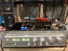
I am new to the forum, but with help I've already received from AK I was able to return a Yamaha CR-640 to life. There's still some work to do, but I got it up and running...for a while.
When I inherited this unit, I could not power it on. My 300W bulb tester lit up like a roman candle so I powered it down immediately. The transformer checked out good, so I looked at other areas that could draw so much current to light the bulb tester this way. I replaced the output power modules with new STK0050-II's and the short seemed to be cleared up. With the modules removed I noted that the diode between pins 9 and 10 on one of the modules had failed, so it was good that the modules were replaced.
The lamps were all burned out, so I replaced them. I realize that colored LED's are a popular replacement strategy (and for good reasons), but I wanted to retain the original appearance, so I used incandescent bulbs. The controls were all scratchy and have now been cleaned up.
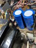
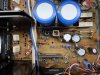
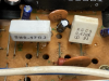
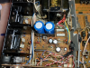
Many of the critical power circuit capacitors have been replaced, but I have another 25 yet to go on the power/audio side. I've heard that the filter capacitors are usually quite reliable. I checked the ESR and they looked OK, but when I checked capacitance they were nearly 20% below spec (around 8,000uf instead of the the rated 10,000uf). As a result, I replaced the filter capacitors. One of the larger power board capacitors appeared to be leaking so I replaced all of the larger ones.
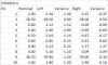
For a while the the receiver was working and sounded very nice. Checking on the scope, the sine waves looked smooth, but with a tiny bit of noise in the tips of the curve at higher power levels. The volume level was so high when I was starting to see some noise that I decided to defer until I can run the unit with a dummy load so that I can drive it to clipping without blowing out my ears. I built a dummy load box, but I need to make some cables to connect to the receiver.
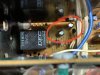
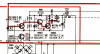
After running for a bit, the protection relay would no longer energize. I replaced the most obvious protection circuit transistors TR904 and TR903, and I replaced capacitors C901 and C902. C902 is rated at 47uf, but I measured nearly 200 uf, so this was a definite problem. I checked the other protection circuit components and all was good, intermittently, but there are times when the protection relay will still not "click." Since the plan was to recap anyway, I am hoping that this will fix the issue. A relay is on order and will be replaced upon receipt. With the protection circuit stable, the unit should be good to go.
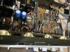
I counted nearly 50 capacitors in the tuner section and no doubt they should be replaced. The FM tuner still works, but signal strength is weak. Frankly, I am out of my league when it comes to the tuner section, and since so few people listen to FM on vintage receivers, I am planning not to recap the tuner section unless it quits completely.
Cosmetically, the unit is in excellent condition, so while this receiver has only moderate market value, I think it is worth the effort to get it fixed.
Any thoughts or feedback are appreciated.
I am new to the forum, but with help I've already received from AK I was able to return a Yamaha CR-640 to life. There's still some work to do, but I got it up and running...for a while.
When I inherited this unit, I could not power it on. My 300W bulb tester lit up like a roman candle so I powered it down immediately. The transformer checked out good, so I looked at other areas that could draw so much current to light the bulb tester this way. I replaced the output power modules with new STK0050-II's and the short seemed to be cleared up. With the modules removed I noted that the diode between pins 9 and 10 on one of the modules had failed, so it was good that the modules were replaced.
The lamps were all burned out, so I replaced them. I realize that colored LED's are a popular replacement strategy (and for good reasons), but I wanted to retain the original appearance, so I used incandescent bulbs. The controls were all scratchy and have now been cleaned up.
Many of the critical power circuit capacitors have been replaced, but I have another 25 yet to go on the power/audio side. I've heard that the filter capacitors are usually quite reliable. I checked the ESR and they looked OK, but when I checked capacitance they were nearly 20% below spec (around 8,000uf instead of the the rated 10,000uf). As a result, I replaced the filter capacitors. One of the larger power board capacitors appeared to be leaking so I replaced all of the larger ones.
For a while the the receiver was working and sounded very nice. Checking on the scope, the sine waves looked smooth, but with a tiny bit of noise in the tips of the curve at higher power levels. The volume level was so high when I was starting to see some noise that I decided to defer until I can run the unit with a dummy load so that I can drive it to clipping without blowing out my ears. I built a dummy load box, but I need to make some cables to connect to the receiver.
After running for a bit, the protection relay would no longer energize. I replaced the most obvious protection circuit transistors TR904 and TR903, and I replaced capacitors C901 and C902. C902 is rated at 47uf, but I measured nearly 200 uf, so this was a definite problem. I checked the other protection circuit components and all was good, intermittently, but there are times when the protection relay will still not "click." Since the plan was to recap anyway, I am hoping that this will fix the issue. A relay is on order and will be replaced upon receipt. With the protection circuit stable, the unit should be good to go.
I counted nearly 50 capacitors in the tuner section and no doubt they should be replaced. The FM tuner still works, but signal strength is weak. Frankly, I am out of my league when it comes to the tuner section, and since so few people listen to FM on vintage receivers, I am planning not to recap the tuner section unless it quits completely.
Cosmetically, the unit is in excellent condition, so while this receiver has only moderate market value, I think it is worth the effort to get it fixed.
Any thoughts or feedback are appreciated.