• The move to the new server is done. There are some software and database maintenance updates in process. This has us passing the hat around to help out. We appreciate any donations. Seriously, even a dollar helps. The payment page may be found here - https://www.audiokarma.org/support.html

Yamaha M-80 Protection/Restoration

RyeGuy859

Well-Known Member
Hello all! Just picked up a M-80 for a screaming deal and i’m very excited to tear into it. Owner said it doesn’t come out of protect after sitting for a few years so i’ll be looking at the glue and other corrosion once i get into it first. It’s serial 12933 so no need to make any additions as in the technical bulletins. This is going to be more of a light restoration thread plus some questions depending on the problems I find within. Giving the outside a look over i see a few things. First it looks like new binding posts are definitely in order. I’ll be picking up some plexiglass shortly. Secondly, the voltage selector is set to 110v. I reside within the US where we use 110-120v so should i set this is 110v or 120v? I assume the difference is small but should be corrected.
 
Register to hide this ad
I suggest fixing the malfunction first... Measure the DC voltage out of each amplifier. ( DC offset ) .. Find a test point before the relays. Should be < 250mv. The closer to zero the better.
 
This is the easiest DC offset test points. Using mini grabber multimeter clips. Use the black & red wires on each side. There labeled E & R as well as E & L..
Caution :D Do not short circuit TP E to the adjacent wires. Or you will very very likely " Chernobyl " and amplifier . Definitely will " take out "" hard to find " output transistors.

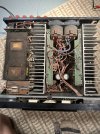
1694131353336.png
 
Last edited:
Well some good news! Left channel was .016v and Right was -.004 (may have had my leads reversed wasnt paying enough attention). I checked a few other number and at the top of each amp board I had a 90vish wire and a 39vish wire (dont remember the exact values).

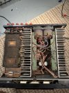
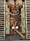
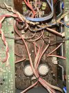
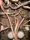
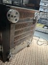
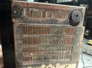
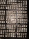
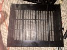
On the other side of things this amp is very dirty. I'll give her a good suck and blow and see where that gets me. Looks like it was somewhere very moist., perhaps when sitting in the garrage for years. Ill definantly be refinishing the bottom cover. The glue didnt look to aweful. A few components completely covered, but as i poked at it it flaked off. Not sure the best way to get at it. Desolder the caps and do my best or remove the entire amp board, but that will be after we solve the protection issue.

Here are some pictures for your enjoyment. It was missing a plastic foot, so i threw on some aluminum ones I had extra. Gives it a bit more clearance underneath.
 

Attachments

  • 607CB852-EABC-4988-A0A8-F50FA7295E0A.jpeg
    607CB852-EABC-4988-A0A8-F50FA7295E0A.jpeg
    201 KB · Views: 92
  • 017C41A4-3C80-40DD-BF0D-1DA339D09F57.jpeg
    017C41A4-3C80-40DD-BF0D-1DA339D09F57.jpeg
    179.2 KB · Views: 92
  • E88606DD-DAF9-4DD5-8E81-30DA3220D145.jpeg
    E88606DD-DAF9-4DD5-8E81-30DA3220D145.jpeg
    186.7 KB · Views: 90
  • 159E9C57-E3AA-4C14-BEB4-B0AE21C3C8BC.jpeg
    159E9C57-E3AA-4C14-BEB4-B0AE21C3C8BC.jpeg
    179.7 KB · Views: 85
  • 34314CA4-6EB5-44C1-8D5F-0832930AE9A3.jpeg
    34314CA4-6EB5-44C1-8D5F-0832930AE9A3.jpeg
    170.8 KB · Views: 85
  • BBF9781F-A800-4518-A48C-54D61F059BC3.jpeg
    BBF9781F-A800-4518-A48C-54D61F059BC3.jpeg
    150.5 KB · Views: 84
  • DF49E0F2-A060-4786-B729-5DB3337B57EF.jpeg
    DF49E0F2-A060-4786-B729-5DB3337B57EF.jpeg
    198.5 KB · Views: 89
Well some good news! Left channel was .016v and Right was -.004
That's great news.. Bad news. Its one corroded mess.. I guess the best course of action now would be a good cleaning first. So we can see the darn thing and have a close inspection of component leads for corrosion. Most likely you will find D119 or D120 zener diode with missing leads due to corrosion. Another place to look is the jumper leads along side the copper buss bar. Have a good look over the bottom side solder connections. I'd charge twice as much to clean up a mess like that.
Must of had this in a frick'n barn..:thumbsdown:

Pretty funky look'n feet. :biggrin:
 
Last edited:
Having that low offset, would point towards the amp board being okay? No matter how corroded its current state is. So to fix the problem before I get into cleaning ill be looking at the relay board? and perhaps the apu boards? Maybe it would be better to just tear it down, clean and reflow everything first. It may just solve the issue.

Im not sure where the feet came from. Someone had them on a small Kenwood unit and the reciever wasnt much taller then the feet themselves! So I took them off and theyve been floating around since. Gonna have top wait and see how they look when its on the shelf.
 
Not as bad, There is a light rust ring on the inside i’ll probably sand and paint.
 

Attachments

  • 1B763EAD-6E62-4105-855A-EE82E7689AAA.jpeg
    1B763EAD-6E62-4105-855A-EE82E7689AAA.jpeg
    229.1 KB · Views: 19
  • B76714C7-351A-40F3-809C-FC4C85FD506B.jpeg
    B76714C7-351A-40F3-809C-FC4C85FD506B.jpeg
    164.2 KB · Views: 18
  • 47C2B479-CB3E-4548-815D-C1F62424898B.jpeg
    47C2B479-CB3E-4548-815D-C1F62424898B.jpeg
    169.6 KB · Views: 19
Having that low offset, would point towards the amp board being okay?
correct
So to fix the problem before I get into cleaning ill be looking at the relay board? and perhaps the apu boards?
Muting/Protection circuit on the main board as well as the relay board and relay switches ( Speaker select switch's )

Need to verify that the relay operating voltages are getting to the relays.
 
The spring on the meter selector is sticking so i’ll be digging into the front panel anyway. I’ll clean some switches and give it all a reflow. Might have enough room to clean the glue and corrosion just by pulling the two caps.
I’ll take a look at the m-85 schematic and see if there’s any strange voltages around the muting/protection circuit
 
So i got antsy and started poking around. At The 1000uf/100v caps on the main amp board. I believe they’re c163/162 I have 80v at one and .6v at the other. Measuring from ground to the top of the cap (I believe the outside of the cans are connected to the negative?) I reflowed them with no change. Are these fed right off the rail voltages? Im guessing it’s a bad trace or joint leading to them that’s causing my issue.
 
Measuring from ground to the top of the cap (I believe the outside of the cans are connected to the negative?)
Not and ideal method. One of those caps has the positive connected directly to ground and the negative to the negative rail voltage.
 
Didn’t think a dirty selector switch could cause it to stay in protect?
At least one of the selector switches needs to be depresss. Three selector switches ---> three relays. What I was getting at. Is that these are part of the protect relay circuitry.
 
Okay yes, I see that now on the schematic about the caps. I didn’t have a high def one until now so i couldn’t really tell before. I just assumed they were mirrored.

I don’t believe i had any of the speaker selectors switched depressed. But that would just mean no relay not the protection light being on i assume. So still trouble somewhere. I just ordered all the required replacement parts as per this post.


Next step is to check relay/power supply voltages?
 
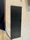
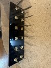
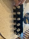
I got a new binding posts plate made and installed. When testing continuity between the posts I have .3ohms between CL and all 6 ground posts. and 9ohms between CR and ground. around 5-6ohms between the two L and R. I’ve double checked my soldering and within those two boards there’s nothing even close to bridging. If i check between CR and ground and tap the left most relay (I assume it’s for C) I jump between 9-100ohms randomly sometimes with no connection at all until i tap it again.


I know some of these are in series, so is this behavior normal? I assume tapping the relay part is not and means the contacts inside are a bit dirty.

I have no connection between CL/CR+ and BL/BL+ or AL/AR+
 

Attachments

  • BC2535BD-EBCE-4879-AC2C-355604ED2A0D.jpeg
    BC2535BD-EBCE-4879-AC2C-355604ED2A0D.jpeg
    121.2 KB · Views: 17
  • 3D0CDC76-2725-46BB-93C9-ECE1C1677560.jpeg
    3D0CDC76-2725-46BB-93C9-ECE1C1677560.jpeg
    135.7 KB · Views: 18
  • A5B7CFD6-FBF4-4FE5-8D3E-3458C2A5D8CB.jpeg
    A5B7CFD6-FBF4-4FE5-8D3E-3458C2A5D8CB.jpeg
    131.3 KB · Views: 17
Back
Top Bottom