SonicTemple
New Member
After benefiting from the work of others for years, I've finally decided to give back to the community. I recently purchased a set of vintage Yamaha NS-344 speakers off eBay. They're in really good condition but I noticed when listening that the right midrange speaker wasn't producing much sound. I swapped the right for the left and there still wasn't much sound coming from it and the right speaker in the left cabinet sounded fine (so its not the speaker). I also swapped the mid level pads and still not much sound coming out of the right midrange speaker (so not the level pad). Really the only thing left is the crossover and so down the rabbit hole I went.....
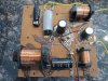
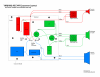
I'm a 'do it myself' kinda guy with limited electrical experience but I can normally figure things out eventually. I started by removing the woofer and inspecting the crossover on the back of the cabinet. Everything looked normal. No loose wires. No leaking/bulging capacitors. I was really hoping there was something obvious but there wasn't. I looked online for a schematic for the crossover so I could figure out which capacitor(s) were inline with the midrange but couldn't find anything. So I drew one up along with a crossover layout. I put them into TinyCad and attached them here for future reference to all. I couldn't find any info on the inductors (maybe its stamped on the bottom). If anyone knows or sees an error in my drawings or has a recommendation for something to add, let me know.
This'll be my first post, I'll add others as I work my way through removing the crossover and replacing the capacitors.
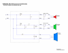
I'm a 'do it myself' kinda guy with limited electrical experience but I can normally figure things out eventually. I started by removing the woofer and inspecting the crossover on the back of the cabinet. Everything looked normal. No loose wires. No leaking/bulging capacitors. I was really hoping there was something obvious but there wasn't. I looked online for a schematic for the crossover so I could figure out which capacitor(s) were inline with the midrange but couldn't find anything. So I drew one up along with a crossover layout. I put them into TinyCad and attached them here for future reference to all. I couldn't find any info on the inductors (maybe its stamped on the bottom). If anyone knows or sees an error in my drawings or has a recommendation for something to add, let me know.
This'll be my first post, I'll add others as I work my way through removing the crossover and replacing the capacitors.
Last edited: