amr2
Well-Known Member
Yes, by laser or waterjet cutting.You were going to have them fabricated?


Yes, by laser or waterjet cutting.You were going to have them fabricated?

Yes, by laser or waterjet cutting.


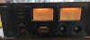
The PC2002M is a classical design using full complementary common-emitter push-pull output power stage. I've had one for last 20yrs now and connected to any JBLs, and a Luxman pre, the combo is unbearable.
It developed some protection issues which I fixed, but accidentally fowled the +/-15V supply which feeds a lot of low level circuitry, including the VU meters, and one channel of meter Ic IG00137 got partially damaged.
Anyone have idea where to get the MD meter board or the Ic ?
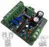
Fully working !
If you open up the IG00137 black box, i think its just regular through hole parts in there with two opamps. You may be able to rebuild the circuit. Check out this post regarding a similar black box, the IG00136.
Alternatively, you might be able to use an "aliexpress special" dual analog VU meter driving board in place of your black box. you'll just have to feed it the correct voltage.
View attachment 2429281
How did you fix it so fast? I need those skills.
How did you fix it so fast? I need those skills.

Thanks mike, appreciate a lot !Here's the link to the thread on the meter board.
https://audiokarma.org/forums/index.php?threads/pc2002m-meter-board.812767/