OK. I know I once had some of that de-soldering wick stuff, but so far I can't find it. Where should I look to buy replacements for those? I think it's obvious that they have leaked.Yes.. The only way to inspect the underside.. It is likely no longer glue..


You are using an out of date browser. It may not display this or other websites correctly.
You should upgrade or use an alternative browser.
You should upgrade or use an alternative browser.
Yamaha R-50
- Thread starter Hamm
- Start date

Either that or someone spilled something in there.OK. I know I once had some of that de-soldering wick stuff, but so far I can't find it. Where should I look to buy replacements for those? I think it's obvious that they have leaked.
What µf and voltage are they ? What diameter and length in mm are they ?
There is no sign of anything spilled on their tops or sides. Only seemingly coming out from underneath.Either that or someone spilled something in there.
What µf and voltage are they ? What diameter and length in mm are they ?
50v - 6800 UF
25mm dia - 50mm height.
I double-checked all my measurements. I believe they are correct. The first time through, I began numbering the pins from the wrong end. I believe the second round is correct. Post #40. Go by those.Bit busy, will try and find time later.
A quick look shows pin 12, right channel output at -40V!
Pin 15 is due to -40V feedback?
The first set of measurements suggested a problem with the left channel, your pin 4 actual pin 5 = 40.4V = left output.
Last edited:
Going to want to scrub that dark /crusty portion of the circuit board as clean as possible. Address any oxidation of component leads and jumper leads. Caused by the leakage.
Last edited:
Pins 12 & 13 are the standout faulty results.
High pin 13 voltage may correspond to low current draw, ie an open.
I don't see a pin to pin test that would confirm the open. You could try
a diode test, red probe on pin 10 black probe on pin 14, amp powered off/unpluggesd, expect 2xVbe, 1.4V
Maybe others with better eyes will pick something up.
High pin 13 voltage may correspond to low current draw, ie an open.
I don't see a pin to pin test that would confirm the open. You could try
a diode test, red probe on pin 10 black probe on pin 14, amp powered off/unpluggesd, expect 2xVbe, 1.4V
Maybe others with better eyes will pick something up.
Well, I ordered the capacitors and wick from Mouser. They don't show having the STK, but other sites do. Should I order that as well? I'll try performing that diode test, but most of this goes right over my head. Baby steps. I mean, I do generally know what a diode does, but beyond that lies a dark abyss...
Last edited:
Diode allows current flow in one direction (of the "arrow") and blocks flow in the reverse direction (hence the bar). They are multifunctional from providing a simple 0.65Vdc drop to bias transistor/Vbe tracking duties to rectification to ... Diode test (diode symbol on MM) is a common procedure for testing transistors. Nice graphic from markthefixerI do generally know what a diode does
Attachments
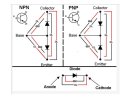
My original inference was that a "diode test" would be the testing of a diode. I now see I was mistaken. Baby steps...
OK. I did some searches and reading until I understood how to run that "diode test". I got approx 1.5 - jumping around just above and below that value.You could try
a diode test, red probe on pin 10 black probe on pin 14, amp powered off/unpluggesd, expect 2xVbe, 1.4V
I'm not entirely clear on just what is being tested there, but that's what I got.
Last edited:
If you download a copy of the STK4873 datasheet you will find an equivalent circuit on page 2. The test was for pin 10 & 14 so looking at the equivalent circuit for a path between 10&14 you will see a b-e path via the VAS(?) transistor and another b-e path. If either of these transistors had failed then this would give you a different result, test is limited to the b-e junction, does not cover the c-e junction. I suspect that the vas transistor (with the cap) has failed c-e short(?) or maybe one of the driver transistors."diode test". I got approx 1.5 - jumping around just above and below that value.
I'm not entirely clear on just what is being tested there,
Years ago I messed with some of this type of thing after a neighbor guy gave me a Heathkit tuner he had built. I still have it. I believe one channel is out and I have some recollection of what component was suspect. I intend to look into that after I get through with this Yamaha (if).
Is that version of the datasheet on this site? could you link me to wherever it is? I'm not finding a useful version of it.If you download a copy of the STK4873 datasheet

Sparkplug
Super Member
Is that version of the datasheet on this site? could you link me to wherever it is? I'm not finding a useful version of it.
Attachments
The datasheet contains a logical/equivalent diagram of the STK. The transistors I mentioned are part of the STK "internals"Should I lift the legs of any specific transistors to check them more directly?
PS: Would the failure of that transistor you mentioned take out the STK?
Get used to googling xxxx datasheet pdfIs that version of the datasheet on this site? could you link me to wherever it is? I'm not finding a useful version of it.
Yeah, I had done that, but didn't find one which looked like this one. Got it now.Get used to googling xxxx datasheet pdf
Been busy with other things, but I'll get back to studying it.
Oh, so not accessible. Got it. So is the STK fried, then? If so, can we deduce a cause? Could those bad/leaking caps be related? I have read that these STKs can be a bit fragile. Could it just fail with no outside cause? I was playing the system pretty loud, but I've done that many times. Was driving a pair of JBL control 1's. I believe they are 4 ohms. I have also read that this tuner/amp was/is good at driving low impedance loads, if that's the right way to say it.The datasheet contains a logical/equivalent diagram of the STK. The transistors I mentioned are part of the STK "internals"
I have seen this STK listed for sale. Is there a specific source I should use or are they all pretty much the same?
Last edited:

audiotemp
Super Member
Is this what your speaker connections look like? (This is from thr R-50 user manual.)Was driving a pair of JBL control 1's. I believe they are 4 ohms. I have also read that this tuner/amp was/is good at driving low impedance loads, if that's the right way to say it.

Do you see where it says speakers should be 8 to 16 Ohms?
Who told you the R-50 could drive 4 Ohm speakers?
Last edited: