• The move to the new server is done. There are some software and database maintenance updates in process. This has us passing the hat around to help out. We appreciate any donations. Seriously, even a dollar helps. The payment page may be found here - https://www.audiokarma.org/support.html

Yet another butchered 250

goldswimmerb

Failed out of engineering, but look at me now!
Subscriber
Alright, so some of you guys probably remember my last thread on the 250M that was toasted, that one went smoothly and was a great learning experience all round.

Anyway, I have a new challenger now... A Marantz 250 that's been very much molested. Right now I am trying to assess the damages, it actually worked and came out of protect and passed a signal, but for obvious reasons, it can't be trusted, so I am making a new post to help with research and ideas...

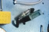
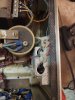
Below are pictures of the patient:
20210407_224746.jpg
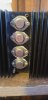
Hot glue for lamp holders... Nice...
received_1034281477102903.jpeg
Obvious fake output Transistors are obvious...
20210407_230157.jpg

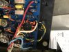
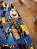
Anyone got any ideas on this abomination? Assuming it isn't factory but like what...
20210407_230145.jpg

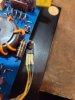
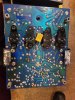
Is that cap supposed to be there?

20210407_224759.jpg
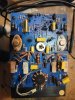
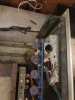
Where's my 2nd trimmer at... Anyone have a part number for a replacement? Also, one emitter resistor isn't matching... Should the replacement be a non-inductive part?
Also, what's up with the bias block having been replaced with a single Transistor? Is that able to be done on these?

Any help is appreciated, I've been wanting to jump into another one of these, but am unfamiliar with the differences between the 250 and 250M
 

Attachments

  • 20210407_224750.jpg
    20210407_224750.jpg
    86.1 KB · Views: 73
  • 20210407_230206.jpg
    20210407_230206.jpg
    88 KB · Views: 74
Register to hide this ad
Also, what's up with the bias block having been replaced with a single Transistor? Is that able to be done on these?
I have one with same issue. Same board version as yours. There is a device that has been recommended here in some threads, MJE180G. I’m curious as well if that will do the job all by itself.
 
I have one with same issue. Same board version as yours. There is a device that has been recommended here in some threads, MJE180G. I’m curious as well if that will do the job all by itself.
I think it should, looks like the box package may have a diode though
 
I would exercise caution replacing the bias transistor with MJE180 in this particular version. I am currently working on a 1200 that has the diode across Q507 (I believe) and I pulled it out to check. It has a hFE above 500 which MJE180 doesn't come close (around 120). This may be important given its role as a multiplier. The diode is a 1N542 (germanium) and I have some left.

In your picture:

upload_2021-4-8_8-23-21.png

As for the yellow "abomination" that in fact is factory - look for C801 in the SM. The board I am working on was apparently blow torched so it melted with the socket but still gives a proper reading of 0.1uf.

upload_2021-4-8_8-22-11.png
 
I would exercise caution replacing the bias transistor with MJE180 in this particular version. I am currently working on a 1200 that has the diode across Q507 (I believe) and I pulled it out to check. It has a hFE above 500 which MJE180 doesn't come close (around 120). This may be important given its role as a multiplier. The diode is a 1N542 (germanium) and I have some left.

In your picture:

View attachment 2187933

As for the yellow "abomination" that in fact is factory - look for C801 in the SM. The board I am working on was apparently blow torched so it melted with the socket but still gives a proper reading of 0.1uf.

View attachment 2187932

The abomination stack on the front side isn't factory though right? It's like a cap across a resistor and one cap in series with a resistor in parallel
 
The abomination stack on the front side isn't factory though right? It's like a cap across a resistor and one cap in series with a resistor in parallel
Absolutely not! Interestling enough I had R530 (which I believe belongs to that spot) blown to smithereens so we may be facing a similar issue.

As for your missing pot - that could be a tough thing to replace. I read somewhere that the 2W requirement may be overkill for that application but I didn't take the time to calculate the current that goes through it. I can see it was replaced by two resistors in an attempt to make it work but I wonder how you would get DC balance that way.
 
Absolutely not! Interestling enough I had R530 (which I believe belongs to that spot) blown to smithereens so we may be facing a similar issue.

As for your missing pot - that could be a tough thing to replace. I read somewhere that the 2W requirement may be overkill for that application but I didn't take the time to calculate the current that goes through it. I can see it was replaced by two resistors in an attempt to make it work but I wonder how you would get DC balance that way.

The answer is you don't get adjustable DC balance, it was stuck at 150mv or so... The shop that did this sh*t is still in business, almost tempted to call them and ask what the f***
 
@goldswimmerb a quick calculation on the back of an envelope gives me 104V across two resistors and the trimpot (14.2K total) so you are looking at 0.7W. If you can find a 1W pot that would be close but I think doable.
 
See the bulletins that tonebells posted earlier in this thread.
Holy cow the photo he posted has a similar contraption. I couldn't find the values or procedure in the bulletins, will keep looking.
 
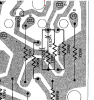
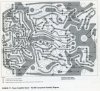
A better scan of the board layout. Component side.
 

Attachments

  • Schematic021.jpg
    Schematic021.jpg
    196.9 KB · Views: 54
See the bulletins that tonebells posted earlier in this thread.
Do you know if inductance (or lack thereof) on the .15ohm wirewounds is critical? One was wrongly swapped with a .2ohm so I am going to replace them all.
 
I have this same board in one of my 1200s. It is working but I have not been able to get the bias to come up more than a few mv. I will be following along to see how this one goes.

Tony
 
I have this same board in one of my 1200s. It is working but I have not been able to get the bias to come up more than a few mv. I will be following along to see how this one goes.

Tony
What transistor and diode are you using? I measured the original (working) transistor inside the epoxi and its hFE was very high - more than 500. The MJE180 seems only to work with Q521 ( MPS6519 ) versions (no diode).
 
Back
Top Bottom