well it would be 34V after the rectifier. so 14.4V at 25A. soooo 19.6V x 25A = 490W.
This is some general information to help you with your calculations.
Remember that when you are in the design stage the 34 volts is what the filter capacitors charge to, it is the peak voltage. What you are concerned with is the RMS voltage in terms of power dissipation. As soon as current is drawn from the power supply the voltage on the filter capacitors will start to drop. There will also be a voltage drop due to the losses in the transformer.
It is not likely that at full current (25 amps) that the voltage drop across the pass transistors will be 19.6 volts.
Below is a ball park example of what you might expect.
Note in the picture below The current (green line) is about 24 amps and the usable voltage is about 25 volts. The would cause about 275 watts of dissipation for the pass transistors. Somewhat less than your 490 watts. This is based on ballpark numbers for you transformer and filter capacitors.
It shows the voltage on the filter capacitors under your full load.
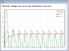
If the current drawn is reduced by about half, the available voltage will increase to maybe 28 volts and the power dissipation of the pass transistors would be about 168 watts.
Again these are just ballpark numbers, but they will give you an ideas of what is happening.
Again you can not count on the peak voltage being available under full load Below is an example with a 12.6 VAC transformer.
Note the actual voltage available at full load, about 24 amps.
Again, the peak voltage that you are using is only going to show up in the filter capacitors when there is no current being drawn from the power supply. This is a ballpark example with a 12.6 volt transformer.

Again, note the available voltage (the red trace). And again these are ballpark examples using normal numbers for the transformer, diodes and filter capacitors, but they give a good indication of what to expect.