• The move to the new server is done. There are some software and database maintenance updates in process. This has us passing the hat around to help out. We appreciate any donations. Seriously, even a dollar helps. The payment page may be found here - https://www.audiokarma.org/support.html

Yet Another Minimus 7 Upgrade Thread - Coronavirus Edition

drp1003

Well-Known Member
Yes, yes. It's been done a million times before, but I guess I got bored waiting for the the world to end so I decided to upgrade a pair of Minimus 7s I had laying around - the speaker terminals and crossover networks.

In what is now looking like a minor miracle, my pair of crossover network PCBs and pair of banana plug speaker terminals I ordered from Amazon just before the the fall of civilization happened, finally showed up in the mail yesterday. Rain or shine or pandemics, the US Mail is still sending me junk mail as well. Just kidding. Thank You USPS! Your service is very much appreciated! And FED EX and UPS!

Anyway, I upgraded the crossover networks and the speaker terminals, PHOTOS BELOW

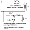
The crossover network has a 12dB slope for the tweeter (cap and coil and resistor for padding) and the woofer gets one coil for a 6dB taper. Crossed at 3500 hertz, I think, if I remember correctly.

All I had to do was fabricate a new bracket: A piece of 3/16in thick fiber board with six drilled holes. I reused the speaker wires from the old crossover networks. Pretty easy.

These tiny little super speakers are hilariously good in their stock configuration, but with these tweaks, they really shine.
 

Attachments

  • 0326200942[1].jpg
    0326200942[1].jpg
    67.5 KB · Views: 414
  • 0326200942a[1].jpg
    0326200942a[1].jpg
    56.4 KB · Views: 392
  • 0326200950[1].jpg
    0326200950[1].jpg
    60.3 KB · Views: 385
  • 0326200956a[1].jpg
    0326200956a[1].jpg
    51.4 KB · Views: 378
Last edited:
Register to hide this ad
I'm sure it's been covered before, but could you detail the improvements you hear after the upgrade?
I think I hear most of the improvements coming from the woofer. Before, in the stock configuration, the woofer was operating at its full frequency range, with no attenuation at all - no coil to block out the high frequencies. Which means that the woofer was reproducing some of the same frequencies as the tweeter.

Now with the woofer getting attenuated because of the coil, I hear a bigger fuller sound coming from the woofer (the midrange). Like a room-filling sound. Once you get used to the sound, it's really quite striking. These would make great surround speakers.

Also, I should add one more thing. The tweeter is getting knocked down a notch by that resistor. Which also makes the midrange stand out a bit more....
 
Last edited:
Any chance of a schematic, or a list of parts and values? :biggrin:

From Amazon:

(1 SET) Jabinco 2pcs Gold Plated Insulated Terminal Binding Post Power Amplifier Dual 2-Way Banana Plug Jack

(1 SET) uxcell 2 Pcs 130W 2-Way Speaker System Audio Crossover


You'll need to get a pair of wire terminals for each speaker - four total. The ones that are round in shape with a hole in the middle. Those are for running wire from the banana speaker terminals to the crossover input +/-

Nuts and bolts to secure the crossover PCB to the bracket.
 
Is that crossover designed specifically for the Minimus 7 or is it a generic crossover?
This is a crossover that is made in China, and if I had to guess, it is a clone of a crossover that is used in a popular speaker made by Polk or Klipsch or whatever. The resistor that is part of the tweeter crossover section kinda gives it away. Usually a generic crossover would have just caps and coils, and the buyer would then have to add all of the other things like L-pads and zobel RC circuits.
 
This is a crossover that is made in China, and if I had to guess, it is a clone of a crossover that is used in a popular speaker made by Polk or Klipsch or whatever. The resistor that is part of the tweeter crossover section kinda gives it away. Usually a generic crossover would have just caps and coils, and the buyer would then have to add all of the other things like L-pads and zobel RC circuits.

Is there a reason you went with a substitute crossover instead of one designed specifically for a Minimus 7?

I have three pairs of Minimus 7. I bought the Minimus 7 crossover from ebay for my first pair. It made an improvement. I use them for computer speakers.

I bought the parts for the PZ-2.1 crossover for my other two pairs. I have not yet built it, but I have high hopes.
https://www.audiokarma.org/forums/i...akers-measurements.199790/page-4#post-2352576
 
I have a couple pair of Minimus 7W(sealed) and the only thing I’ve ever done to them is add a little bit more stuffing to try and lower the Qb and Fb. In the enclosures my 7s can only get down to 110Hz flat. I currently use one pair as my rear surround speakers and the other pair with a Sansui G-3500. Has anyone ever built a larger cabinet for them? I’ve always wanted to try a TL or back horn loaded cabinet with them to try and get some more bass and efficiency out of them.
 
Is there a reason you went with a substitute crossover instead of one designed specifically for a Minimus 7?

I have three pairs of Minimus 7. I bought the Minimus 7 crossover from ebay for my first pair. It made an improvement. I use them for computer speakers.

I bought the parts for the PZ-2.1 crossover for my other two pairs. I have not yet built it, but I have high hopes.
https://www.audiokarma.org/forums/i...akers-measurements.199790/page-4#post-2352576

I was gonna follow that ZILCH M7 crossover thread to its bitter end, buy all the recommended crossover components separately through Parts Express, and build a pair of crossovers myself, but the more I thought about it, and the more shopping around I did online, the more I realized that just buying those two items I used (from Amazon) was the easiest AND CHEAPEST way to go.

Just put those two items in the cart and press BUY NOW. Done and done. I still had to fabricate a bracket; I realized that at the time, but the bracket was gonna be a lot easier to make - six drilled holes in a small piece of fiber board.

I've had good luck with Chi-Fi in the past. I don't have anything against Chi-Fi. The stuff is cheap. In the end, if this whole experiment would have failed, then I would have just thrown those crossovers in the pile with the rest of my electronic stuff, and there they would wait until I came up with another harebrained scheme.
 
Last edited:
Would adding in an inductor for the woofer and adding a resistor to the stock tweeter circuit achieve the same thing :dunno:
 
Would adding in an inductor for the woofer and adding a resistor to the stock tweeter circuit achieve the same thing :dunno:

Here's the schematic, traced off of PCB images posted on amazon.com.

View attachment 1808860

Inductor values shown are reported by Amazon reviewer RhythmJunky. Method for determining values is not reported, so take it for what it's worth.
Oh OK. I may have the parts around here to duplicate that if I ever get the time :idea:
 
Here's the schematic, traced off of PCB images posted on amazon.com.

View attachment 1808860

Inductor values shown are reported by Amazon reviewer RhythmJunky. Method for determining values is not reported, so take it for what it's worth.
Thanks for doing that work :thumbsup:
Now we can compare this crossover to the one designed in another AK thread:
index.php

The relevant thread is this:
https://www.audiokarma.org/forums/i...us-7-loudspeakers-measurements.199790/page-43
 
Back
Top Bottom