• The move to the new server is done. There are some software and database maintenance updates in process. This has us passing the hat around to help out. We appreciate any donations. Seriously, even a dollar helps. The payment page may be found here - https://www.audiokarma.org/support.html

Zenith MM2604-4

I forgot to mention "Mouser electronics" but as far as salvageable is concerned, definitely YES! The capacitors don't have to be exact so maybe try looking for something along the 400 volt line, and all 3 can be the same.

If you were to get all 3 at say 300 MFD @ 400 volts, they would work. It is always ok to go up but never down in specs. Never go below the 200 volt spec.
 
Good luck on your rebuild John! I'll be following along with your thread.

I picked up the exact same console yesterday.
 
Good luck on your rebuild John! I'll be following along with your thread.

I picked up the exact same console yesterday.

Cool. If you find some brass drawer pulls that look like the one I'm missing (for the speaker louvers), please let me know... Otherwise, I'm just going to change them both out with something that doesn't look too odd.
 
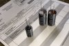
OK. Parts are in, so new round of questions commences now... Each capacitor has two, bare wires, about an inch long, protruding from one end. One is slightly longer than the other. Which one is the ground (black)? And should I try to buy some heat-shrink plastic insulation to go over these, or just put some ordinary black electrical tape over the exposed wire?
 
They should be marked on each end or on the sides with either a + symbol or - symbol.

If you have heat shrink stuff, that will work great. If not, electrical tape will work in a pinch. Just make sure that no bare wires are shorting or grounding to the chassis.

Let's see a pic of the new capacitors then we can show you for sure which ends are negative and positive.
 
Since you're a novice, you wouldn't really know how to read these things but the short wire is the negative (-) and it shows (to us seasoned folks anyway lol) that the negative side is marked on the side of the capacitor as that entire white strip on the one side. Those are actually negative symbols. These will all be attached together like my previous pic shows using the individual capacitors.
 
Houston, we have lift-off! FM radio is working great, although there's still a bit of background hum at higher volumes. AM is less so (i.e., it is not working so well -- lots of static). Wonder if soldered connections would have been better... Now on to the turntable. Everything from the bottom looks intact. Almost new, in fact. I can scratch my finger across the needle and hear the sound on the speakers. But nothing is moving. My suspicion is that the belt has disintegrated -- when I was vacuuming the interior, I noticed quite a bit of black debris directly beneath the turntable. What I'm not sure about is how to remove the platter to check. I do have the manual so that's where I'll start, unless you already know. I really appreciate your help getting me this far along!
turntable.JPG Manual only covered changing needles, so no help there. Am also wondering if the tuner face should be illuminated. I'll look at the parts list from the schematic and see what I can tell from that...
 
Last edited:
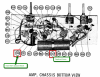
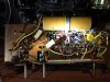
There is a hum in the system when the record player is turned on (it may be there, in the background, for the radio also). The hum gets louder when I turn the volume up... There are two capacitors I did not change on the amplifier -- could that be the source of the hum?

capacitors_-_parts.png amplifier_-_from_schematic.png amplifier.JPG
 
I normally change out all caps except for the mica ones. You might also try reversing the plug in the socket, just to eliminate that as a cause. The tuner is usually illuminated so the bulbs may be burnt out. This model is the lower end model in Zenith's line but still is a good performer. I suspect that at 55 or so years old she is due for a proper restoration, which you've already begun. Your changer looks like a rim drive by VM and will need to be rebuilt. I might have a service manual on this but I need the changer's model # which can be found underneath. Definitely worth restoring. You won't be disappointed.
 
Thom, you might want to jump over to my thread in the turntable forum... I'm a bit further along (but just a bit) there... I looked for bulbs in the schematic but not on the parts list -- I'll look again. Are there LEDs that can replace the original? Also, over on the turntable forum I've uploaded what I think is the model # from the interior of the console.
 
Last edited:
Most of those series string (hot chassis) amps and tuners didn't have any pilot or tuning dial lamps unless it was tapped off of the rectifier tube. Your schematic is correct in which it does not have any.
 
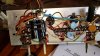
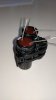
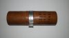
Hi all! For anyone who happens on this thread, a 2018 update from another newbie. I bought the same model from a local family, mostly as furniture because it we loved the the mid-century modern style and it fit perfectly in an empty space we were looking to fill. Since it powered up, I was interested in seeing if it could be repaired. I searched around a bit an d ended up on this thread. My unit had the same buzz that John Ragland described in his OP. So I read further. I followed the advise of the experts on this forum and low and behold, it's back to life! The links to buy the correct capacitors were even still valid! So thank you very much for sharing! I zip tied the replacement capacitors together before soldering the connections. Also, if you want, after snipping the old capacitor wires, you can get the old capacitor out by gently rocking it back and forth until the aluminum retainer breaks at its connection to the chassis - images attached. This is a surprisingly good00000IMG_00000_BURST20180823123855_COVER.jpg IMG_20180823_122618.jpg sounding unit, well worth the effort. Thanks again!!
 

Attachments

  • IMG_20180823_120338.jpg
    IMG_20180823_120338.jpg
    29.8 KB · Views: 46
Back
Top Bottom