• The move to the new server is done. There are some software and database maintenance updates in process. This has us passing the hat around to help out. We appreciate any donations. Seriously, even a dollar helps. The payment page may be found here - https://www.audiokarma.org/support.html

Zilch's AK Design Collaborative - Econowave Speaker

Remember the focus has been primarily on two way, woofer tweeter. This has been discussed earlier in the thread, steering lobes(?) and the only way to integrate the tweeter w/ woofer is to measure the drivers with the crossover.

Avoid the wank...follow the Zilch plan...prototype, test, modify, test, finalize, test...:thmbsp:

Sound pressure is not the same as controlled directivity....:scratch2:

I will :) But i don't think that what Wayne P. and Linkwitz are doing with driver spacing is wank :)
 
Last edited:
The crossover was designed/tested with the waveguide as close as possible to the woofer, that's why it's the recommendation (aside from reasons why it may generally be a good plan).
 
I just thought that if he is building new cabinets, he could calculate driver spacing taking xover point in to consideration. It was talked about long time ago...

attachment.php


Regards...:beerchug:
 

Attachments

  • Vertical_Null_Angles.gif
    Vertical_Null_Angles.gif
    16.1 KB · Views: 698
DIY Wooden waveguides for Zilchwave speakers

I just posted a thread over at Techtalk about making conical "not too far from OS" waveguides from MDF and plywood. Worked out pretty well, and should be a good fit for 2-way designs particularly if you want to make a special size that might not be otherwise available (mine are 18"x10", 80x40 degrees). I'll avoid the major crosspost and just put some teasers and the design spreadsheet here.
WaveguideTest.jpg


Horizontals:
Pix3.jpg


Verticals:
Pix4.jpg


I did a spreadsheet to calculate the dimensions of the main pieces, attached. (page 1 only, ignore the other 2 pages which didn't work out well)

Hope someone finds this helpful
 

Attachments

Last edited:
Does anyone know if it is still possible to obtain the Zilch crossover boards?

Hey Joe, I think someone here has taken up the charge and is or will be offering them. I've built 4 pairs of eWaves so if you need help, let me know.
 
At last the OLAs are EWaves!

I hope everyone will forgive a long first post, but I thought a few notes on my Original Large Advent (OLA) to EWave conversion might help someone -- and I'm pleased to have gotten through the project!

I'm truly sad to have arrived here just after the passing of Zilch, who seemed a true village elder in the best sense: wise, tolerant, learning and teaching abundantly. It was only after I started to read through the EWave threads here and at AudioHeritage that I realized how much thought, research, and discussion went into the deceptively simple EWave design, and I'm sorry not to be able to thank him for that. But I do want to thank all the other EWavers, and especially Bauhausler, whose OLA conversion guide steered me past several potential land mines.

I've had a pair of OLAs in storage for longer than I can remember, and I finally put new surrounds on the woofers. The surrounds were from Parts Express and apparently are the narrower type that can raise the woofers' resonant frequency to 40+ Hz, but the space between the masonite ring and the cone seems too small to take anything wider, and they sound very good to me after the repair. (I'll post a set of measurements before and after the EWave conversion when I get the data entered.) The speakers are unmatched -- one has a dark front panel, the other a light one -- but they both have masonite-ringed woofers and sounded similar to me before and after the conversion. They have "utility" cabinets that I plan to refinish with "Band-It" cherry paper-backed veneer.

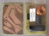
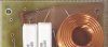
I wasn't sure if the EWave circuit boards were available, but I had an ancient Radio Shack DIY circuit-board kit sitting around anyway, so I made a template from posted photographs of the board, simplified it slightly by eliminating the jumpers for bi-amping, and as the Radio Shack boards were a little smaller than Zilch's I moved the iron-core coil off the board to the other side of the big capacitor. Whether from corrosion over time or insufficient time in the etching solution, one board conducted between the "islands," but some crude work with a Dremel routing bit solved that problem.

attachment.php


attachment.php


The opening in the OLA's back for the terminals and the high-frequency control is about 3" (7 cm or so) square, so I decided, like Bauhausler, to put the binding posts and the L-pad control into it without further cutting into the thick particle board. It's a squeeze, but it fits. I thought the wires would probably lead upward so I put the posts over the L-pad knob, but that may have been a poor call. Given the space constraints, I should have ignored the instructions that came with the binding posts, which said to align the posts so the wire holes run top-to-bottom. Side-to-side would have been easier to thread. I'll wire up double-banana-post connectors to the speaker leads when I install the speakers, though, so it won't matter.

attachment.php


The circuit board construction was the most time-consuming part of the project, but (as can be seen from the photos) I'm no wizard with a soldering iron, much less a master board-etcher. To my surprise and delight, the boards worked fine without any resoldering. Getting them mounted with the proper clearance for the nuts that connect the binding posts electrically as well as mechanically to the board took a little experimenting, but after shimming things with a scrap venetian-blind slat and moving the L-pad (which I'd put so close to the board that it couldn't be mounted) it all worked out.

Using Bauhausler's invaluable measurements as a guide I hacked away at the cabinet with a hand-held jig saw and, when I broke my last blade, a hole-cutting drill bit, a hand-held rotary saw, a Dremel cut-off wheel, a sanding bit, and a hammer. It was not elegant carpentry, but the Polk Audio horn fit well and with a little Mortite rope caulk I got a good seal. I didn't add a foam plug to the horn as he suggests, but my high-end hearing isn't what it used to be, so I don't mind a little high-treble emphasis. I attached the crossover board to the back of the cabinet with Amazing Goop Wood Contact Cement and added a couple of wood screws for good measure. (Hint: it's easier to remove the old controls by chiseling from the back than by trying to lift the staples from inside.)

Following the instructions that came with the Selenium compression driver, I attached the supplied clips to the high-frequency leads from the crossover. I tried that for one woofer as well, but by the time I desoldered and cleaned the woofer terminals and got the clips soldered to the low-frequency leads I decided it just wasn't worth it. I just attached the woofer's black (negative) and green (positive) leads to my crossover leads with the little wire binders (what are they called?) that I salvaged from the original crossover assembly. Bauhausler recommends adding stuffing to the original ration of fiberglass that is in the OLAs, but with one speaker I simply couldn't fit any without compressing it to the point where I think it would have hindered the movement of the woofer cone. I added a third of a bag of Parts Express nylon fill into the other. I don't hear a difference, but I'll have to measure that one and compare it with my numbers from the first one.

The result: the speakers sound dramatically good to me, with what I'd describe as smooth, deep bass and very clear midrange and high frequencies. As I said, I've taken some measurements (with my extra-high-end $20 eBay old-type RadioShack sound meter, model 33-2050) and I'll try to get them up soon after I adjust for its nonlinearities and make some charts. I've found a new favorite test record, too: Philip Glass' soundtrack for Martin Scorcese's Kundrun. It's got both acoustic and electronic music, Western and Tibetan instruments and chants intermixed, and an incredible range of sounds, from deep drums to tiny bells. It sounds great on the Econowaves. I hope my neighbors forgive me.

attachment.php
 

Attachments

  • Board_routed_one-third.jpg
    Board_routed_one-third.jpg
    112.4 KB · Views: 682
  • Boards_one-third.jpg
    Boards_one-third.jpg
    126.9 KB · Views: 686
  • Level_control_one-third.jpg
    Level_control_one-third.jpg
    123 KB · Views: 679
  • OLA-EW_No_1_completed.jpg
    OLA-EW_No_1_completed.jpg
    131.7 KB · Views: 686
Last edited:
Nice Work!

I hope everyone will forgive a long first post...
I wasn't sure if the EWave circuit boards were available, but I had an ancient Radio Shack DIY circuit-board kit sitting around anyway, so I made a template from posted photographs of the board, simplified it slightly by eliminating the jumpers for bi-amping, and as the Radio Shack boards were a little smaller than Zilch's I moved the iron-core coil off the board to the other side of the big capacitor. Whether from corrosion over time or insufficient time in the etching solution, one board conducted between the "islands," but some crude work with a Dremel routing bit solved that problem.

attachment.php

...

I've found a new favorite test record, too: Philip Glass' soundtrack for Martin Scorcese's Kundrun. It's got both acoustic and electronic music, Western and Tibetan instruments and chants intermixed, and an incredible range of sounds, from deep drums to tiny bells. It sounds great on the Econowaves. I hope my neighbors forgive me.
Long post is good.

As to the board, yep, it came out of the etchant too soon, or it had gotten weak. Was that the second board or the first? It looks like you started with double-sided boards too. That takes more time in the bath too. There is some copper on the top side still that may cause shorts. The dremel routing bit might be a good idea there too. Just go around each hole to isolate the component leads from the copper.

I'll have to look that Phillip Glass soundtrack up...

Forgiveness. It's easier than asking permission..
 
Last edited:
Thanks, Mike!

Yup, that was the second board I etched. But I also left it in for a much shorter time. I'd gotten distracted and left the first one in for nearly an hour, then got impatient, looked at the second after 15 min or so, decided it looked done and pulled it. I should have known better after all the photographic prints I've made that looked great under the red darkroom safelight but really were too pale!

After finding the shorts in the second board I went at the first with my multimeter too, checking all possible combinations of the "islands" for a short, but it seemed OK. I hope the electrons don't tunnel a new path...
 
I just posted a thread over at Techtalk about making conical "not too far from OS" waveguides from MDF and plywood. Worked out pretty well, and should be a good fit for 2-way designs particularly if you want to make a special size that might not be otherwise available (mine are 18"x10", 80x40 degrees).

[snip]

I did a spreadsheet to calculate the dimensions of the main pieces, attached. (page 1 only, ignore the other 2 pages which didn't work out well)

Hope someone finds this helpful

Very cool, thanks for posting this.
 
Thanks, Mike!

Yup, that was the second board I etched. But I also left it in for a much shorter time. I'd gotten distracted and left the first one in for nearly an hour, then got impatient, looked at the second after 15 min or so, decided it looked done and pulled it. I should have known better after all the photographic prints I've made that looked great under the red darkroom safelight but really were too pale!

... I hope the electrons don't tunnel a new path...


They don't tunnel but they do build bridges! (Well, you're not using any diodes, so...)

Here's the area that might be bridged when you're not looking.
 

Attachments

  • Boards_one-third.jpg
    Boards_one-third.jpg
    9.1 KB · Views: 46
Thanks very much for doing the image edit to illustrate the danger spot; that's the area that worries me a little too. I'll listen for any changes -- I imagine I might have to pull the board sometime in the future, though I don't look forward to it. I've entered the frequency data I took right after construction, so at least I have a reference point. (I'm a little hesitant to put the charts up, as they principally reveal how bad my measurement methods were, that is, how enormous the room effects were!)
 
Last edited:
The crossover was designed/tested with the waveguide as close as possible to the woofer, that's why it's the recommendation (aside from reasons why it may generally be a good plan).
I just thought that if he is building new cabinets, he could calculate driver spacing taking xover point in to consideration. It was talked about long time ago...

foofighter, I don't have the guts to get into the math. makes me feel stupid. always a poor student.

we seem to have multiple opinions here. can we come to a consensus? what is the correct spacing for this combination of driver, waveguide and crossover?
 
foofighter, I don't have the guts to get into the math. makes me feel stupid. always a poor student.

we seem to have multiple opinions here. can we come to a consensus? what is the correct spacing for this combination of driver, waveguide and crossover?

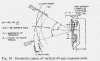
Wayne said we should make baffle spacing so that the null angles are just outside the horn's vertical pattern.

Regarding the xover and being tested for specific (closest possible) mounting of the driver, it's just partially true. +95dB and -95dB xovers are just very good starting points for designing xover that will work fine with midbass that we are going to use. Check out Techtalk "Flex your PCD mettle"... There are few combinations of JBLclone WG and D220ti. For every specific midbass/tweeter combination, xover is different.

Regards Z...
 
Last edited:
My comments on driver spacing were directed at someone using one of the "kit" designs, so the crossover was in fact optimized for the system there. I could swear Zilch said that all the 12" "kits" have spacing that might as well be as close as possible, but maybe I made that up because I can't find it. I haven't done the math.

The math via Wayne is here: http://audioroundtable.com/PiSpeakers/messages/11054.html (but you can't entirely use it aside from feeling out the algebra without basically doing what you see in the "flex your PCD mettle" thread). Can we agree that if you don't do all of this to try to get the absolute best vertical control, too close is the side to error on, at least unless you are using a very small midwoofer?

Here's a pretty good layman's summary of the issue from Wayne too: http://www.audiokarma.org/forums/showpost.php?p=1983065&postcount=568
 
Last edited:
............Can we agree that if you don't do all of this to try to get the absolute best vertical control, too close is the side to error on, at least unless you are using a very small midwoofer?

......................

Of course. That is great tip for someone who is not going to do the calculations.

foofighter...............

we seem to have multiple opinions here. can we come to a consensus? what is the correct spacing for this combination of driver, waveguide and crossover?

If acoustical xover frequency is 1600Hz, then spacing between the centers of speakers should be arround 12" for 90*40 waveguide.

Wavelenght λc = speed of sound (344m/s) / frequency
Wavelenght λc = 344m/s / 1600Hz = 0.215m

d1 - (center to center distance)

α = arcsin(λc/2*d1)
α = arcsin(0,215m/0,6096m)
α = arcsin(0,3526902) = 20,65
2α= 41,3 degrees

Arcsin(x) calculator here - http://www.analyzemath.com/Calculators_2/arcsin_calculator.html

Here is Wayne's example...

Wayne said:
Using Linkwitz formula, the Theater Series four π speaker's asymmetrical 1600Hz crossover and tweeter-midwoofer spacing of 13.25" yields

d1 = 0.33m (13.25") between the tweeter center and the midwoofer center
λc = 0.22m (8.5") wavelength of 1600Hz
a = 19o or 2a = 38o (arc between nulls)

This is equal to the vertical dispersion of the HF horn. The nulls are set at the edge where HF dispersion falls off.

Regards, Z...
 
Last edited:
Back
Top Bottom