
Does anyone know the difference between Yamaha B2 driver boards NA-06747 and NA-06811? I've got an NA-06747 driver board that bias and Idling current float around on so I pulled a good driver board from another B2 with one dead side to get my amp up and running while I trouble shoot the driver board. I put the new board in and adjusted bias and idling current and they hold rock solid. The only issue is the VFET heat sinks on the side with the replaced board runs hot ..134 degrees while the other side is around 88 degrees or less. Then I noticed that the board I pulled out (the one that wasn't holding bias) was an NA-06811 while the replacement board I put in the amp was a NA-06747. (The other board in that amp is a NA-06811 also) Without checking part for part for differences the only difference I see is the part number (NA-06811) and a sticker on it that says "Caution-For Continued Protection Against Fir Hazard, Replace With The Same Yamaha Fusing Resistor. The service manual only refers to a NA-06747 driver board with no mention of a replacement. I have a couple of other B2's and they all use the NA-06747. The old board that I pulled out did not cause the heat sinks to get any warmer than the right side, just let the bias and idle float. Any thoughts/help would be appreciated.

You are using an out of date browser. It may not display this or other websites correctly.
You should upgrade or use an alternative browser.
You should upgrade or use an alternative browser.
Yamaha B2 Driver Boards - NA-06747 vs NA-06811? Difference
- Thread starter endeeinn
- Start date
Does anyone know the difference between Yamaha B2 driver boards NA-06747 and NA-06811? I've got an NA-06747 driver board that bias and Idling current float around on so I pulled a good driver board from another B2 with one dead side to get my amp up and running while I trouble shoot the driver board. I put the new board in and adjusted bias and idling current and they hold rock solid. The only issue is the VFET heat sinks on the side with the replaced board runs hot ..134 degrees while the other side is around 88 degrees or less. Then I noticed that the board I pulled out (the one that wasn't holding bias) was an NA-06811 while the replacement board I put in the amp was a NA-06747. (The other board in that amp is a NA-06811 also) Without checking part for part for differences the only difference I see is the part number (NA-06811) and a sticker on it that says "Caution-For Continued Protection Against Fir Hazard, Replace With The Same Yamaha Fusing Resistor. The service manual only refers to a NA-06747 driver board with no mention of a replacement. I have a couple of other B2's and they all use the NA-06747. The old board that I pulled out did not cause the heat sinks to get any warmer than the right side, just let the bias and idle float. Any thoughts/help would be appreciated.
Welcome to the forum
yes, there are different serial numbers for the driver boards as it is for the PSU boards too.... but a far as I can tell, the boards are identical. The board with the black sticker is from a US version amp. Japan probably for the other.
the fact that the Bias or DC float around has to do with something else, but not the board version. For the bias floating around, I wold first check that trim pot. That could be a serious problem that can cost you a v-fet or two...swapping driver boards can also ruin your day....
Thanks for the reply. That's what I was afraid of, after comparing the boards I came to believe that they appear to be the same and I've come to the conclusion that the PS board needs a closer look and those trimmer pots on the PS are on my list to replace. I am getting the proper output voltage on the PS but the VFET voltage is under 10v on that left side. I've already replaced all the trim pots on the driver boards with burns 10 turns. Plan is to figure whats wrong and get the original board back in.
wait 10v less wherePS but the VFET voltage is under 10v on that left side.

there are two separate voltages going to the driver boards:
+/-85V regulated, coming straight from the PSU board shared by both driver boards. If these were missing 10v in one board and the other was OK, I would look at your wire connections....The PSU trim pots are not the main suspects if one driver board has correct voltages.
+/- 56-60v unregulated that would vary a little based on your mains voltage and it is separate between the left and right. This basically comes in straight from the Big cans board below and you can measure it between the red/white and black wire at the terminal posts of the vfet assembly boards, where white to black = (-)56v; red to black = +56v and red to white = (white to black + red to black) = ~112v
which voltage are you missing 10v from? DO not plug that amp back with Vfets attached until you have rock solid supply.
wait 10v less where
there are two separate voltages going to the driver boards:
+/-85V regulated, coming straight from the PSU board shared by both driver boards. If these were missing 10v in one board and the other was OK, I would look at your wire connections....The PSU trim pots are not the main suspects if one driver board has correct voltages.
+/- 56-60v unregulated that would vary a little based on your mains voltage and it is separate between the left and right. This basically comes in straight from the Big cans board below and you can measure it between the red/white and black wire at the terminal posts of the vfet assembly boards, where white to black = (-)56v; red to black = +56v and red to white = (white to black + red to black) = ~112v
which voltage are you missing 10v from? DO not plug that amp back with Vfets attached until you have rock solid supply.
It's the 56/60-V that is about 10v low on the left (problem) side, the +/- 85v seems rock solid. As stated above driver board trimmers are burns 10 turn and the 1st thing I did when having the bias problem was to replace both trimmers with new ones. Next steps are to remove the VFets and driver board both sides and and recheck the 56-60 with VFETS out and go from there depending on what I find. All caps have been replaced including the 4 large PS caps.
Weather is now favorable so some yard work to do now but rain is in the forecast in the coming days so will get back to it then. Thanks for the help and support!
Removed the VFET's and voltage across the red/white is 119v solid on both channels. The left channel was the one running hot and the VFET sockets on the left side were black and won't clean with contact spray. Wonder if thermal grease burned with the heat? Maybe the poor contact caused higher current draw and high heat in the left channel? Traced the VFETS below...I'm no expert but the left side traces seem OK while the right side that played fine shows the 2SJ26's as questionable (I think).
Attachments


These are more of the traces
Attachments


clinic-audio
all on YAMAHA untill 1990
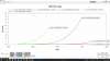
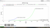
Yes , stranges curves for some 2SK76 (3) and one 2SJ26 is dead
Yes , stranges curves for some 2SK76 (3) and one 2SJ26 is dead
maybe...First, he is not holding the test parameters locked when comparing DUTs. Second, the DCA75 is not intended to test power devices. The tests results can be misleading.
Yes indeed and agreed! The DCA75 is certainly a nice tester for smaller semi's but when it comes to these guys it's barely even tickling it on so to speak. If clinic is using his to decide whether they're bad or good I want to go and rummage around in his waste bucket.maybe...First, he is not holding the test parameters locked when comparing DUTs. Second, the DCA75 is not intended to test power devices. The tests results can be misleading.
")
Rottalpha is right, I didn't lock the parameters. I'll recheck locking parameters though if the DCA75 isn't a good way to check VFETs I don't know what it will tell me. If not the DCA75, what is the best way to check?Yes indeed and agreed! The DCA75 is certainly a nice tester for smaller semi's but when it comes to these guys it's barely even tickling it on so to speak. If clinic is using his to decide whether they're bad or good I want to go and rummage around in his waste bucket.
belgianbrain
Super Member
Yes indeed and agreed! The DCA75 is certainly a nice tester for smaller semi's but when it comes to these guys it's barely even tickling it on so to speak. If clinic is using his to decide whether they're bad or good I want to go and rummage around in his waste bucket.
LOL.
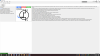
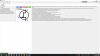
I checked all the VFETs using the DVM method described elsewhere in the forum. Attached are the results. They all appear to be similar so all bad or all good? Didn't do anymore with the DCA75 as I could get deferring results depending on the test voltage ranges used. Should I let the DCA75 'autoset' or use a specific set of test voltage ranges and lock them in? 
My original problem was with the left channel and the left channel 2SJ26's seem a little mismatched..should they be considered bad?
My original problem was with the left channel and the left channel 2SJ26's seem a little mismatched..should they be considered bad?
My original problem was with the left channel and the left channel 2SJ26's seem a little mismatched..should they be considered bad
not considered bad nor mismatched. You have no way of knowing if they are matched or not. You will also not know by using a DCA. You need a curve tracer that Ideally can reproduce operating conditions for the vfets, then compare the curves. You cannot get that from DCA75....not for power devices.
If you did not mix the vfets, the factory matching is more than you can achieve on your own, so your worry should be the well-being of the vfet, rather than matching.
The burned up connector of the driver board is worrisome. Luckily, the +/-85v which supplies gate current and it is the lifeline of those vfets, comes to the driver board via the orange and green wires, which are soldered to the boards.
You cannot know if you are out of the woods yet, but based on the DMM test, it looks like you might have gotten lucky. If you are concerned, and in lieu of an adequate curve tracer, in order to further test the well-being of the vfet,you could use the method described on Amplimos website. You would have to reverse polarity of your PSU for P-channel devices (2SJ26).
With that said, if you use the Amplimos described test technique, don't forget to use adequate heatsinking for your DUT to be safe!so your worry should be the well-being of the vfet, rather than matching.

Last edited:
After a summer of projects I got back to the B2 and it's up and running again. As reported above the sockets for the TO-3 VFETs were black and burned so I replaced all R & L with new ones. Looks to me like whoever removed and replaced the VFETs sometime in the past got some thermal paste on the contacts causing the burned/blacked contact surfaces .. just a guess. Also replaced the 2SC458 refrigerator transistors on the power supply board with NOS 2SC458 non-refrigerator transistors. All voltages check and hold steady. Re-installed all VFETS and original driver board. Amp seems to run fine now. Heat sinks temps on both sides run at about 103 degrees and hold within a couple of degrees. Set bias and DC balance after about 30 min warm up and now able to set bias on left side which was my problem in the first place although is varies from 39 to 41 mv have a 10 turn burns pot in place and that could be it and will replace at could be cause for variance - DC balance rock steady at 0 mv. The right side bias is rock steady at 40mv as well as DC balance at 0mv. My guess is the 2SC458's where the problem with no bias adjustment on the left side and the burned sockets the cause of the high temps. Have no way of checking distortion but I'm using it for a summed subwoofer and both meters track and both subs sound like equal output. Switched it to my mid output running Altec 416's and it sounds fine, no different than the amp that was driving it and I switched it back to sub duty. Listening as I'm writing and all sounds as good as it ever did. Hope this is a permanent fix and don't have to muscle that amp around anymore as my back can't take much more. Thanks to all for there contributions and please don't hesitate if you think I still have a little more work to do on it or that I'm off base with my conclusions. Thanks again to all!
Similar threads
- Replies
- 0
- Views
- 310