

You are using an out of date browser. It may not display this or other websites correctly.
You should upgrade or use an alternative browser.
You should upgrade or use an alternative browser.
Pioneer M-90 Recap
- Thread starter Matt03221
- Start date

Matt03221
Active Member
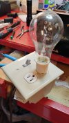
If you search the AK site for Dim Bulb Tester you'll find lots of examples and instructions on how to build. Here's a pic of mine. It's a life saver.Answer you is difficult for me , but I'm sorry if you have problems! Can you show me your db tester?
Attachments
Last edited:
Matt03221
Active Member
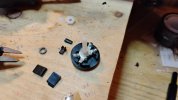
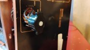
Figured out a way to hold the switch together. Also had to file some notches in the back panel slot to secure the switch since the clips broke of as well. Unit fires up fine, but the burn spots on the switch contacts worry me a bit. Anyone have any thoughts on that? I've never pulled one of those apart before- is that normal wear and tear or something else?
Attachments



today I waiting all other capacitors , starting from the cap around the protection circuit...
your Dim Bulb Tester is very beautiful ! Do you connect it to the wall socket and connect the amplifier to the free plug that I see to lower the input voltage to the transformers?If you search the AK site for Dim Bulb Tester you'll find lots of examples and instructions on how to build. Here's a pic of mine. It's a life saver.
Matt03221
Active Member
Yes, you plug this into the AC wall socket and plug the device into the open socket on the DB tester. A dim bulb tester functions as a current limiter and safety device for testing electronics. By placing an incandescent light bulb in series with the device under test, it restricts excessive current flow. If a fault, such as a short circuit, exists in the device, the bulb will glow brightly, indicating a problem and preventing further damage.today I waiting all other capacitors , starting from the cap around the protection circuit...
your Dim Bulb Tester is very beautiful ! Do you connect it to the wall socket and connect the amplifier to the free plug that I see to lower the input voltage to the transformers?
Attachments
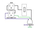
So in my case , if I connect the DB tester to m-90 , current that flow in the amply is less (depend on the bulb installed in )but current is lower than I can cheke if the protection circuit is still ON or change his status ...... (?...!???) the only problem is the ground .....
Matt03221
Active Member
I didn't install the ground lead pictured. Some designs don't have that. I will also add that I'm not an expert on weather that's critical. I can only say it's not caused me any issues.So in my case , if I connect the DB tester to m-90 , current that flow in the amply is less (depend on the bulb installed in )but current is lower than I can cheke if the protection circuit is still ON or change his status ...... (?...!???) the only problem is the ground .....
Matt03221
Active Member
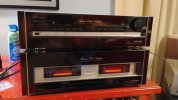
I'm gona call it good. Based on the discussion in this thread: [https://audiokarma.org/forums/index.php?threads/pioneer-m-90-draws-100w-when-idle.950813/], I think it safe to say those arch burns on the voltage selector contacts are likely caused by a loss of integrity in the switch combined with the high current draw of the amp. Pic of the thing all back together with the matching preamp I recapped just prior to working this. Relays were replaced a few years ago. Cap replacement was a bit of a pain on that, especially on the lower video PCB that contains part of the power supply. The runs are not very sturdy and easily damaged when replacing components. Here's the cap list for the C-90, as best I recall, if anyone's interested.
AG = Audio Grade; BP = Bi-polar
uf/V (number needed); (*) means I didn’t quite track the actual number needed so I overestimated slightly
470/50 (8)
330/50 (4)
10/50 AG (23)*
22/50 AG/BP (4)
4.7/50 AG (2)
47/16 (7)*
10/25 (21)*
3.3/50 AG (4)
2.2/50 AG (8)
1000/25 (3)
22/50 AG (2)
47/25 (8)
33/50 AG/BP (2)
470/10 (9)
1000/6.3 (1)
100/10 (9)*
47/10 (5)
100/16 (6)
100/25 (8)
22/16 (8)
3300/25 (1)
1/50 (1)
470/35 (2)
4.7/50 (1)
47/35 (2)
AG = Audio Grade; BP = Bi-polar
uf/V (number needed); (*) means I didn’t quite track the actual number needed so I overestimated slightly
470/50 (8)
330/50 (4)
10/50 AG (23)*
22/50 AG/BP (4)
4.7/50 AG (2)
47/16 (7)*
10/25 (21)*
3.3/50 AG (4)
2.2/50 AG (8)
1000/25 (3)
22/50 AG (2)
47/25 (8)
33/50 AG/BP (2)
470/10 (9)
1000/6.3 (1)
100/10 (9)*
47/10 (5)
100/16 (6)
100/25 (8)
22/16 (8)
3300/25 (1)
1/50 (1)
470/35 (2)
4.7/50 (1)
47/35 (2)
Attachments
Last edited:
Matt03221
Active Member
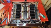
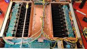
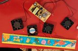
Been running this thing for over a month now with no issues, but like I mentioned before- it does get warm. Each of the (9) heatsinked transistors on the (2) amp cards run at 100 – 110 degrees (F). The (2) main heatsinks for the power transistors run at around 100 degrees (F). With the case installed and this thing in operation that top cover hits 114 degrees easy. BTW, that's idle temps. With that, I thought I’d try to cool it down a bit to hopefully extend the life of the transistors since they are all original. Didn’t have a lot of room to work with inside, especially with that volume control shaft running across one side. I used (4) 40X40X10mm DC fans and an AC to DC converter with a DC output pot ranging from 5 to 12 VDC. Mounted the converter to the inside of the back panel and tied it to 120 VAC after the power switch and mounted the fans to the inside of the bottom panel under the main heatsinks. If I run the fans full speed it drops the surface temp by 40 degrees (F)- a little noisy though. Can’t hear them at normal music listening levels, but it is a little bothersome at very low levels. So, cranked the DC output down a bit so they’re not as noticeable and still get about a 25 degree drop in surface temp.
Attachments
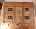

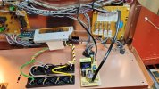
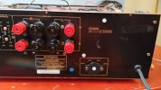

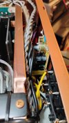
Last edited:
Matt03221
Active Member
So, after the recap this amp has been humming along fine since Oct. However, turned it on the other day and I've now got a 60hz hum in the left channel. Completely isolated it from everything- just the amp and speakers and it's still there. Any suggestions on where to start?

I cannot help, as I am not a tech, but this thread is far too good to only have 2 participants.
Rooting for ya from the sidelines. Always loved that Elite Pioneer gear.
Rooting for ya from the sidelines. Always loved that Elite Pioneer gear.
Matt03221
Active Member
Thanks for the support! : )I cannot help, as I am not a tech, but this thread is far too good to only have 2 participants.
Rooting for ya from the sidelines. Always loved that Elite Pioneer gear.
Matt03221
Active Member
Did you get your's working?Ylli is the right technician to solve the problem !
Did you get your's working?
Matt03221
Active Member
Effort continues here:So, after the recap this amp has been humming along fine since Oct. However, turned it on the other day and I've now got a 60hz hum in the left channel. Completely isolated it from everything- just the amp and speakers and it's still there. Any suggestions on where to start?

Hello, looking for some help with my M-90. I'm getting good audio out of both channels but also getting what sounds like a 60 Hz hum out of the left channel. It starts right after the safety relays kick in. It's in the headphones and at the speaker terminals and it's not affected by the volume control or input selector switch. Don't know if it's related, but I also noticed the left channel DC offset is a bit higher than what I remember- which is 4mv. Right channel still at 4mv but the left channel is now at 8mv. Any suggestions on where to start would be greatly appreciated!!!


