

You are using an out of date browser. It may not display this or other websites correctly.
You should upgrade or use an alternative browser.
You should upgrade or use an alternative browser.
Pioneer M-90 Recap
- Thread starter Matt03221
- Start date

Register to hide this ad

Matt03221
Active Member
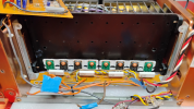
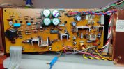
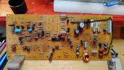
A little scrapped up, but got all the nasty glue off and then reloaded with all new nichicon caps- with the exception of the one oversized wima. This unit is untouched internally as far as I can tell. For some reason pioneer decided not to use heat sink compound on those six transistors, so added that as well. Time to get this back in and move to the next section.
Cap List for this card (uf/v)
330/100 (2); 470/100 (2); 470/50 (1); 470/25 (1); 1000/25 (1); 2.2/100 bi-polar (1); 10/50 (3); 47/25 (5); 100/16 (2)
Cap List for this card (uf/v)
330/100 (2); 470/100 (2); 470/50 (1); 470/25 (1); 1000/25 (1); 2.2/100 bi-polar (1); 10/50 (3); 47/25 (5); 100/16 (2)
Attachments

Last edited:
Matt03221
Active Member
Sorry to hear you're having difficulties. My unit doesn't actually have a problem- it's working fine. However, since it's nearly 40 years old I'd like to keep that way, so thought it time to inspect the internals and change out the caps. Hopefully it will still be good once I'm finished : ) Good luck with yours. I have no experience troubleshooting this particular unit, so I don't have any recommendations.

Matt03221
Active Member
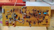
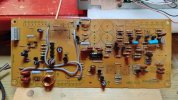
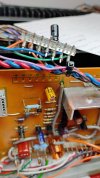
Work on the right channel PCB. Cap List:
470/100 (2); 470/50 (1); 330/100 (2); 330/10 (2); 2.2/100 Bi-polar (1); 47/25 (1); 33/16 (1); 3.3/50 (1) and 22/25 (1) on the upper left connector.
470/100 (2); 470/50 (1); 330/100 (2); 330/10 (2); 2.2/100 Bi-polar (1); 47/25 (1); 33/16 (1); 3.3/50 (1) and 22/25 (1) on the upper left connector.
Attachments



Last edited:
Matt03221
Active Member
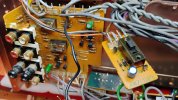
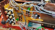
Got the lefts and right CH PCBs back in and got to the caps on the buffer amp and impedance switch PCBs. Buffer amp has (2) 22/50 Audio Grade caps and the switch has a single 10/50. Note: work the buffer amp before you put the R CH PCB back in. I think the lose wiring will give you a bit more room to work with.
Attachments


Matt03221
Active Member
I know what you're thinking: "doesn't he notice those relays on the buffer amp look just like troublesome relays the reck havoc in the C-90?" Actually yes, I did notice and although they are not currently causing a problem, I figured it best to go ahead and replace. So, they're on order along with RY401 and RY402. Thanks to MattiaM's post for providing the part numbers. Now, what to do with those big filter caps....
Last edited:
Matt03221
Active Member
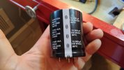
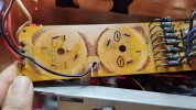
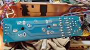
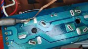
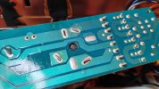
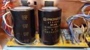
The filter caps. So good looking and likely still decent but just didn't make sense to do all this work and leave 35+ year old caps in there. Took quite a bit of heat to get the solder off there so first had to clip the posts and found it best to use solder wick to get as much solder off as possible- and get as much as possible. Then used pliers to align the post with the slots in the PCB as well as break the connection to the small amount of remaining solder. Then I took a knife to cut the glue, and with a little care- they pulled right out. Got some glue to clean off, but going to use these Cornell Dubilier Knowles 15000uf/100V caps (DigiKey 382LX153M100B062VS). Same diameter but and a bit shorter, but they have 25mm lead spacing so the pins will just fit into those two slots I circled on the board. Same diameter means the copper clamp should still hold them secure. We'll see how it goes.
Attachments



Last edited:
Matt03221
Active Member
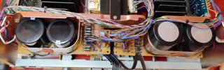
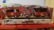
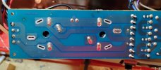
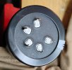
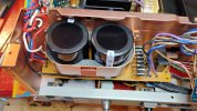
Still waiting for my relays to come in, but thought I’d do a little preliminary work to see how the new caps fit. The caps have (5) pins- 2 positive, 2 negative, and one dummy pin. The 2 pos and 1 neg pins fit in 3 of the 6 slots on the board, so I clipped the other two. Pins are tapered, so the caps sit a few mm of the board. The new caps aren’t quite as wide as the original and due to the pin placement, they don’t quite center in the same spot as the old and are closer together as a result. For that reason, it's good that they sit off the board a bit so the right cap clears the jack between the 2 new caps. The original caps had a hard piece of rubber between them and were clamped, as well as glued, to the panel behind them. The only thing holding the PSBs in place was the caps themselves- glued and soldered to the board. The PCBs were not screw mounted to the frame at all. Since the new caps don’t fit as snug, my plan is to drill holes screw the PCB down to the frame on the back side where there are metal lips to do so (see red arrows). Will likely add some foam inside the copper clamp and to the frame on the backside of the caps to fill in the space and make them a bit more snug. Just need the relays to come in so I can replace them before I wrap this up.
Attachments



Matt03221
Active Member
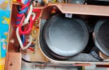
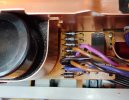
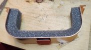
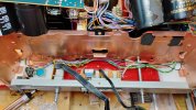
Got the relays in so I finished up the left filter cap PCB and think it turned out pretty nice. You can see where I got the screw holes drilled in the 3 lips. Attached foam to the bracket and the panel behind the caps. Added a nylon spacer between the board and the lips for a little extra safety. All nice and snug and you can see the new relay in there as well.
Attachments

Matt03221
Active Member
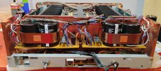
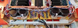
Ran into a slight snag on the right side. Discovered the PCBs aren't mirrored. When I tried the same 3-pin connection- it placed the caps farther apart. On the left side it placed the caps closer together than the originals, which was not a problem. Farther apart and the clamp wouldn't fit around the caps. So, on the right side I had to orient the caps slightly different and could only use one pos and neg pin. Nevertheless, it turned out ok. Now to get those last 2 relays replaced on the buffer amp and wrap this up.
Attachments

Last edited:


Matt03221
Active Member
You must have the M-91 as mine does not look like that and the camps in mine in that same general area are brown. If I do a little research on my part numbers for those- what I find online is they're MICA caps.Can I ask a question since we are working on the same appliance?
What kind of components are these green color. Certainly they are capacitors, but can you direct me what exact type? Are they ceramic? I'm not an expert ...
Matt03221
Active Member
Pulled this parts list from the M91 service manual. Looks like they're likely MICA Caps. The board should be marked with the cap number. Look it up on the attached.Can I ask a question since we are working on the same appliance?
What kind of components are these green color. Certainly they are capacitors, but can you direct me what exact type? Are they ceramic? I'm not an expert ...
Attachments

Matt03221
Active Member
WTF!!! Never had an issue with a recap, so devastated when this appeared to be my first. Fired this up on the DB tester first. Settled in a little brighter than I'm used to, but it came out of protection as normal. At one point the safety light went back to red and then back to yellow but only did that once. No adjustments to check but did look at the DC offset. -1mv on the left, +4mv on the right. Connected a CD, player and everything sounded good on the headphones and a set of speakers. A little nervous with the slightly brighter build and the one flinch of the safety circuit but decided to take it off the DB tester to see what happens. No issue. came out of protection, audio played fine and dandy. Went to check the DC offset and the whole thing died- like it just shut off but no clicks, pops or smoke. First checked for blown fuses- all good. Checked the power switch- good. Started looking for possible crimped wires and did some continuity checks and couldn't find anything. So, plugged it in and started tracing the input voltage and was getting some wired readings. At that point I thought to check the voltage selector switch since it's a multi-voltage unit and the damn thing practically fell apart in me hand. I said before the unit looked untouched internally, but not that switch- it's been tinkered with before and now it's completely fallen apart. I was probably it's last straw when I had to pull the back panel of to get to those relays on the buffer amp- man was that a bitch. Worst part of the whole job. Anyway, I think it safe to say this switch was likely the reason I had the one glitch with the safety circuit. Probably lost connection for a quick second before it completely lost it. Anyway, will have to see about rebuilding this bastard.
![IMG_20250831_145438303[1].jpg](/forums/data/attachments/3459/3459858-eb7eb3a795f3a22bc30efda26452e19e.jpg?hash=636zp5Xzoi)


