Finished!
My Fisher SA-100 clone with EFB II is all finished now. The final steps of finishing out one basic channel, developing and installing the NFB and stability circuits, and then finishing out the other channel are all complete -- as is final testing and documentation as well.
To recap, this project follows the basic topology of the Fisher SA-100 design (GZ34 tube rectification, push-pull 7189 fixed bias pentode operated output stages, 7247 driver tubes for AF amplifier and cathodyne phase inverter, and ~ 20 db global NFB), but uses various parts and pieces from other equipment in the build. The power transformer came from a Fisher X-101 ST, and the OPTs are from a Heath AA-100 7591 integrated amplifier. These OPTs have a lam stack that is identical in size to the transformers used in the SA-100, and have similar impedance characteristics as well. Additional features in my project include the use of a choke that can handle all the current needs of the amplifier, splitting the original 7247 driver tubes into a single 12AX7 and 6FQ7 for practicality, and the implementation of EFB II for pentode based fixed bias output stages. Like the original EFB(tm) concept for UL applications, EFB II not only locks in the output tube bias/B+ relationship regardless of the actual B+ level present, but also maintains the screen/B+ relationship as well -- all in addition to providing fixed bias operation. This means that the lowest distortion operating conditions for the output tubes are maintained regardless of variations in the B+ supply -- be it due to changing AC line conditions, or due to changing dynamic conditions (power output) in the amplifier itself. It is all built on a Hammond chassis. The measured performance is quite high, and speaks for itself:
1. Maximum power output is 20.0 watts RMS per channel, with both channels continuously driven, over a frequency range of 25 Hz to 20 kHz. Under the same test conditions, each channel produces just over 18 watts RMS at 20 Hz.
(Individually driven channel measurements indicate that 22 watts RMS is developed over the same power bandwidth, with no power increase at 20 Hz due to OPT limitations)
2. Total Harmonic Distortion over the 25 Hz to 20 kHz power bandwidth is less than 1.0% within 1 db of 20 watts RMS power output (about 16 watts RMS per channel), with both channels driven.
At 20 Hz, 10 watts RMS is developed per channel with no more than 1% THD, with both channels driven.
3. The frequency response of both channels is +0/-1 db to 70 kHz, measured at a standard 1 watt power output level.
4. Stability is such that no amount of capacitive loading (only) on the output will cause any tendency towards oscillation.
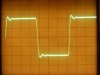
5. 10 kHz square waves display a fast rise time on the leading edge, and well damped wave top. A couple pics are provided below.
6. The clipping characteristics are smooth and even, and recovery from overload is virtually instantaneous.
This is very high performance indeed. After listening to it for about 11 hours now, it displays all the dynamics and sharp detail that the specifications would imply in an effortless fashion, without any tendency towards stridency or muddled bass. Definition is very high over the entire frequency spectrum (that I can hear anyway) through my Cornwalls. It simply provides all the sound so loved from the EL84 family of tubes, but gives every impression of presenting it with the authority of the best 7591 designs.
For my article, I am working with a couple of fellow AKers to include performance data in it from not only my own build, but also from an authentic stock Fisher SA-100, and from a different (but superb) diy build of the original SA-100 design -- again using Heath AA-100 OPTs, but using a very stiff SS power supply instead, and no EFB. This should not only allow comparison of the two diy builds to the original Fisher product, but also of a conventional tube rectified power supply (such as the SA-100 uses) with EFB, versus that of a stiff SS power supply without EFB.
If anything, it should hopefully make for interesting reading, but also describe EFB II in detail, and show how it can easily be applied to literally gazillions of push-pull EL84 amplifiers out there for a nice performance improvement.
The pics provided below include:
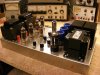
1. On the test bench during development of the NFB and stability circuits. Gotta love alligator clip leads! Numerous components are still just tacked into place.
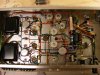
2. The finished build. The testing is all done, and all connections are soldered. Since this was originally a junk box build, some components will likely be changed out later on for higher quality parts (same values), but for now, it's time to enjoy.
3. This is a 10 kHz square wave (left channel in this case, but the right channel is identical) as produced across a resistively loaded output. This is a very good, classic, square wave presentation at this frequency, and indicates many things about the design's frequency response and transient performance. The nearly vertical rise followed by the small hump at the top of the wave is typical of high quality vacuum tube NFB amplifiers, indicating a well extended HF response beyond the traditional audio spectrum, necessary for the application of stable NFB. The wave top is very smooth and straight (without wiggles and bumps), indicating the amplifier's ability to damp itself very quickly after a transient spike such as a square wave represents. Were there numerous wiggles and bumps, it indicates that the design is only marginally stable, with peaks and valleys in it's response curve. These are just some of the reasons that square wave testing is so important (music itself is quite transient as well), and can lay bare so many performance characteristics (good and bad!) of a given design.
4. This is a very rigorous test, and one that many, many of your favorite amplifiers will fail miserably at. This is a 10 kHz waveform, as presented at the output of the amplifier (right channel in this case) -- with no other load than a .25 uF cap connected across the output. It is an important test because long speaker lines, big speaker lines, and complicated speaker crossover networks can represent a significant amount of capacitance placed across the output of the amplifier. I have always maintained that how well a NFB vacuum tube amplifier maintains its composure with difficult loads such as this test represents, will have a greater bearing on the resulting sound produced than any amount of tube rolling, cable/component swapping, or anything else that can be changed out will have. Without a normal resistive load on the output, the amplifier's output spikes as it works to charge the cap on each cycle. But notice that even with so rigorous a test as this, the amplifier maintains it's composure, and dampens out the wave well before the end of the wave form. Many, many amplifiers as originally designed will simply burst into sustained supersonic oscillation with such a test, annoying your neighbor's radio reception, and have you quickly applying for an Amateur Radio's license!
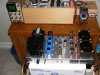
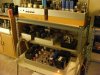
5. Up and running in the rotation. This is a wonderful amplifier to listen to. Even after a full day of operation, the transformers are only warm to the touch, and the amplifier never draws attention to itself. It simply does what it is supposed to do very well. With no signal running through it, it is dead quiet right at the speaker board of the Cornwalls. With a signal applied however, it can make its presence known quite quickly!
I have enjoyed this project immensely. Thanks to all of you who have followed along. A break before the real SA-100 arrives, where then it will be on to testing and evaluating the Fisher's actual stock performance. After that, the article can get underway, and will be published on the Tronola website sometime later this year. Until then, enjoy your projects. Good luck with them!
Dave




 Take a look at this AK thread http://www.audiokarma.org/forums/showthread.php?t=193866&highlight=cats+audio and maybe you'd like to add your cat to the thread. :thmbsp: