

You are using an out of date browser. It may not display this or other websites correctly.
You should upgrade or use an alternative browser.
You should upgrade or use an alternative browser.
Teaser Pics -- Fisher SA-100 clone in progress
- Thread starter dcgillespie
- Start date


thefragger
Certified Crazy.
Quite a remarkable project! I would not have thought that a good test would be for there only to be a capacitor at the outputs.
I'm curious about the details of that little wooden dummy load I see on your bench--what are the reatings of those tube resistors? I picked up four 4ohm, 300W ceramic tube resistors, but never had the nerve to drive them hard, but that little wood holder seems like a great solution to keeping them passively cooled!
I too noticed that awesome looking box, with the knobs + dials behind your amp. Woud love to see a thread about your tester!
:thmbsp: :yes:
:yes: 
I'm curious about the details of that little wooden dummy load I see on your bench--what are the reatings of those tube resistors? I picked up four 4ohm, 300W ceramic tube resistors, but never had the nerve to drive them hard, but that little wood holder seems like a great solution to keeping them passively cooled!
I too noticed that awesome looking box, with the knobs + dials behind your amp. Woud love to see a thread about your tester!
Hi Frannie -- Yeah, the bench and lab was getting a little crowded, so I had to move the amp off the bench to get a better angle for the underside pics.
The stand behind the amp is my power output tube tester. It will test all traditional power output tubes, yielding brutally honest results. It operates a device under test (DUT) with all elements powered from highly regulated power supplies (including the heater), and conducts the test in Class AB1 pentode mode at real world operating voltages (400 vdc) and dissipation levels (70% of design center ratings), using fixed bias operation. This makes the results completely independent of AC line voltage conditions, as well as DUT construction tolerances (and therefore very repeatable), and also very honest. When the test is conducted, the DUT is driven to the onset of clipping (as viewed on the small scope next to it) by an internal signal generator and driver stage. The dvm on the right is then used with an internal peak detector circuit to measure the peak voltage developed at the plate, from which true power output can then be determined. After 20+ years of measuring all manner of new and used tubes with it, I have developed standards of power output for the various tubes it will test, along with an appropriate English scale (Bad-?-Good as a percent of average new power output) to develop an accurate assessment of existing capability, versus that when new. For my own tubes, I can mark their performance from when they are first placed into service, and then track their performance decline over time against their hours of use.
It is really more of a performance tube tester than a traditional tester. All tubes are first run through my Hickok or B&K testers for a general assessment of gas, shorts, or basic operation, such that by the time a tube is placed in the power output tester, it has already passed the basic health tests from my commercial testers.
Thanks for the interest!
Dave
:thmbsp:
:yes: 
Hi Frag -- Thanks for the kind words on this project.
As for the load resistors, I got them many years ago -- before some of the more modern and smaller high power resistors were available. In a nut shell though, those resistors are the resistors as originally supplied in the Heathkit load box that company offered. When I was looking for a good dummy load, that kit was no longer offered by Heath -- but the replacement parts were. So, I ordered the resistors, and built the mount platform. Each one is a non-inductive 8 ohm 100 watt resistor. They are mounted in such a way that if necessary, I can force air through the center of them (they are hollow of course) to aid in cooling, but that has rarely been necessary. With the terminations on the front, I can configure them for 4, 8, or 16 ohms, with a pair for each channel. The terminals across the top allow for feed through connections to the scope and distortion analyzer, etc. Suffice to say, it has served me well over the years.
As for the cap test, I should emphasize that a cap only load test really only applies to NFB amplifiers. For amplifiers without feedback, instability is rarely a concern. But in NFB amplifiers, capacitance in the load (a component of "impedance") can alter the phase shift of the feedback voltage such that it can become positive at supersonic frequencies. When that happens, the amplifier can then develop serious amounts of power that can be very destructive to tweeters. This was the very concern with so many of the early Williamson amplifiers, and earned them quite the reputation for being tweeter killers. As a result, stability issues started getting front row attention, led by no less than David Hafler. Even then, so many of the NFB amplifiers were only marginally stable though that FB eventually got a bad reputation. In reality, it wasn't that feedback was bad, it just wasn't properly applied. The cap only load test is one of those brutally honest tests that either puts proof in the puddin' -- or egg on your face when it comes to HF stability.
Stability becomes an issue at increasingly greater levels of NFB. Designs with 10 db or less NFB rarely have stability issues. But as the levels reach and exceed 14 db, poorly designed NFB loops can invite all sorts of bad manners -- starting with bad sound!
Thanks for the interest!
Dave
As for the load resistors, I got them many years ago -- before some of the more modern and smaller high power resistors were available. In a nut shell though, those resistors are the resistors as originally supplied in the Heathkit load box that company offered. When I was looking for a good dummy load, that kit was no longer offered by Heath -- but the replacement parts were. So, I ordered the resistors, and built the mount platform. Each one is a non-inductive 8 ohm 100 watt resistor. They are mounted in such a way that if necessary, I can force air through the center of them (they are hollow of course) to aid in cooling, but that has rarely been necessary. With the terminations on the front, I can configure them for 4, 8, or 16 ohms, with a pair for each channel. The terminals across the top allow for feed through connections to the scope and distortion analyzer, etc. Suffice to say, it has served me well over the years.
As for the cap test, I should emphasize that a cap only load test really only applies to NFB amplifiers. For amplifiers without feedback, instability is rarely a concern. But in NFB amplifiers, capacitance in the load (a component of "impedance") can alter the phase shift of the feedback voltage such that it can become positive at supersonic frequencies. When that happens, the amplifier can then develop serious amounts of power that can be very destructive to tweeters. This was the very concern with so many of the early Williamson amplifiers, and earned them quite the reputation for being tweeter killers. As a result, stability issues started getting front row attention, led by no less than David Hafler. Even then, so many of the NFB amplifiers were only marginally stable though that FB eventually got a bad reputation. In reality, it wasn't that feedback was bad, it just wasn't properly applied. The cap only load test is one of those brutally honest tests that either puts proof in the puddin' -- or egg on your face when it comes to HF stability.
Stability becomes an issue at increasingly greater levels of NFB. Designs with 10 db or less NFB rarely have stability issues. But as the levels reach and exceed 14 db, poorly designed NFB loops can invite all sorts of bad manners -- starting with bad sound!
Thanks for the interest!
Dave

Rod Beauvex
Look at the tiny bunny...
That wire organization is a wok of art in itself.

I thought I would close out this thread by posting the schematic of the final version and providing some final thoughts. The amplifier has logged about 100 hours now, and has performed flawlessly.
First however, I realized that the power output figures I quoted earlier for the completed amplifier were those from my lab rat tubes and not those provided by the matched quad of Gold Lion EL84 reissues I had received from Jim McShane sometime ago. Credit too many unorganized notes at the time of that posting. In any event, with the GL tubes, individual channel power increased to 25 watts RMS, while maximum power with both channels operating increased to 22.5 watts, for 45 watts RMS total. THD at 1 kHz fell to an incredibly low .05% average at 1 db below full power with these tubes as well. As power output is reduced, distortion continues to fall even further. Not too shabby for an EL84 amplifier, and superb performance from the Gold Lion tubes.
I plan to continue the introduction of EFB II over on the Fisher forum, but lovers of Eico, Scott, Pilot, and a gazillion console EL84 AND 7591 amplifiers might want to follow with interest, as I have now had a real Fisher SA-100 (stock) to throw on the test best to develop some comparative data from, and the results are quite encouraging.
The SA-100 arrived DOA, having not been used in some years. After successfully reforming the can cap, the unit still produced no sound, which was traced to open plate load resistors in the first stage of each channel. Replacing those brought life to each channel again, and a quick check of the remaining components showed that while they were all still in tolerance, there is no doubt that the unit would benefit from some further TLC (matching critical components within each channel and to each channel, etc.).
Against the clone's performance with EFB II, the real SA-100 had credible enough performance in just eeking out 20 watts per channel with similar Gold Lion tubes, but best single channel distortion figures were nearly triple that achieved with the clone, and maximum power with both channels driven was 17 watts with still higher distortion yet -- this as measured at 1 kHz. Additionally, the low distortion point required the tubes to idle with ~ 6 ma more per tube than the clone did, operating the tubes right at the limits of their Design Center dissipation rating. This resulted in just over 30 ma quiescent current per tube, which is in fact Fisher's recommended setting for biasing the amplifier as well. Finally, distortion at lower power levels rose even further, as element voltages all shifted from lowest distortion settings for high power output conditions. Therefore, the stock amplifier does in fact leave room for significant improvement to be had, as had been hoped for -- not the least of which is improving on its well deserved space heater capabilities. This is one hot running amplifier! As a result of these findings, the owner of the SA-100 has requested that I install EFB-II in it for him.
Since the SA-100 is already a fixed bias amplifier, it will require the use of an EFB supply regulator, rather than the EFB cathode regulator used in my clone (because the power transformer offered no tap for a bias supply in it) and SCA/ST-35 amplifiers, but other than that, with installation of EFB II in the SA-100 and my clone, they should both produce nearly identical results. It is this installation in the SA-100 that 7591 users might enjoy, as EFB II for pentode output stages will lower quiescent currents, raise power output, and lower distortion all with a rather simple circuit to boot. With the cost of good NOS 7591s nearly equal to that of gold these days, it could be a very worthwhile modification to pursue.
With that, I will close this thread out with the circuit of my clone (other than to respond to any questions that might arise), and once installation of EFB II gets underway in the SA-100, I will detail that effort on the Fisher forum. After that, I should have plenty of comparative data for my article documenting EFB II in detail, and how it can be added to virtually any traditional push-pull pentode output stage to enhance its performance.
Taking a pic of the schematics was the quickest way I could post them, so I hope they are clear enough to at least give you a good understanding of circuit operation.
Dave
First however, I realized that the power output figures I quoted earlier for the completed amplifier were those from my lab rat tubes and not those provided by the matched quad of Gold Lion EL84 reissues I had received from Jim McShane sometime ago. Credit too many unorganized notes at the time of that posting. In any event, with the GL tubes, individual channel power increased to 25 watts RMS, while maximum power with both channels operating increased to 22.5 watts, for 45 watts RMS total. THD at 1 kHz fell to an incredibly low .05% average at 1 db below full power with these tubes as well. As power output is reduced, distortion continues to fall even further. Not too shabby for an EL84 amplifier, and superb performance from the Gold Lion tubes.
I plan to continue the introduction of EFB II over on the Fisher forum, but lovers of Eico, Scott, Pilot, and a gazillion console EL84 AND 7591 amplifiers might want to follow with interest, as I have now had a real Fisher SA-100 (stock) to throw on the test best to develop some comparative data from, and the results are quite encouraging.
The SA-100 arrived DOA, having not been used in some years. After successfully reforming the can cap, the unit still produced no sound, which was traced to open plate load resistors in the first stage of each channel. Replacing those brought life to each channel again, and a quick check of the remaining components showed that while they were all still in tolerance, there is no doubt that the unit would benefit from some further TLC (matching critical components within each channel and to each channel, etc.).
Against the clone's performance with EFB II, the real SA-100 had credible enough performance in just eeking out 20 watts per channel with similar Gold Lion tubes, but best single channel distortion figures were nearly triple that achieved with the clone, and maximum power with both channels driven was 17 watts with still higher distortion yet -- this as measured at 1 kHz. Additionally, the low distortion point required the tubes to idle with ~ 6 ma more per tube than the clone did, operating the tubes right at the limits of their Design Center dissipation rating. This resulted in just over 30 ma quiescent current per tube, which is in fact Fisher's recommended setting for biasing the amplifier as well. Finally, distortion at lower power levels rose even further, as element voltages all shifted from lowest distortion settings for high power output conditions. Therefore, the stock amplifier does in fact leave room for significant improvement to be had, as had been hoped for -- not the least of which is improving on its well deserved space heater capabilities. This is one hot running amplifier! As a result of these findings, the owner of the SA-100 has requested that I install EFB-II in it for him.
Since the SA-100 is already a fixed bias amplifier, it will require the use of an EFB supply regulator, rather than the EFB cathode regulator used in my clone (because the power transformer offered no tap for a bias supply in it) and SCA/ST-35 amplifiers, but other than that, with installation of EFB II in the SA-100 and my clone, they should both produce nearly identical results. It is this installation in the SA-100 that 7591 users might enjoy, as EFB II for pentode output stages will lower quiescent currents, raise power output, and lower distortion all with a rather simple circuit to boot. With the cost of good NOS 7591s nearly equal to that of gold these days, it could be a very worthwhile modification to pursue.
With that, I will close this thread out with the circuit of my clone (other than to respond to any questions that might arise), and once installation of EFB II gets underway in the SA-100, I will detail that effort on the Fisher forum. After that, I should have plenty of comparative data for my article documenting EFB II in detail, and how it can be added to virtually any traditional push-pull pentode output stage to enhance its performance.
Taking a pic of the schematics was the quickest way I could post them, so I hope they are clear enough to at least give you a good understanding of circuit operation.
Dave
Attachments
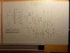
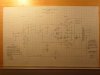

With that, I will close this thread out with the circuit of my clone (other than to respond to any questions that might arise), and once installation of EFB II gets underway in the SA-100, I will detail that effort on the Fisher forum. After that, I should have plenty of comparative data for my article documenting EFB II in detail, and how it can be added to virtually any traditional push-pull pentode output stage to enhance its performance.
Taking a pic of the schematics was the quickest way I could post them, so I hope they are clear enough to at least give you a good understanding of circuit operation.
Dave
If you want to mail the schematics to me, Dave, I'd be happy to scan them and post high-quality images of them, then mail them back to you (assuming they are 8.5x11" paper).
-D
Hi derek -- Yeah, that was my problem, they are on 11 X17 paper. I'm going to see if I can do a better job of it and repost them (maybe using multiple shots). Otherwise, I'm going to have to find a bigger scanner to do the job. Thanks for the offer though --
Dave
Dave
I even tried scanning a half page at a time. Guess I just need to use regular sized paper. I'm so old school, I've just always used the bigger paper, never having to worry about scanners and such!
Dave
Dave

thefragger
Certified Crazy.
I even tried scanning a half page at a time. Guess I just need to use regular sized paper. I'm so old school, I've just always used the bigger paper, never having to worry about scanners and such!
Dave
I keep stacks of that same paper on my desk and I haven't even graduated University yet--it's the best stuff for playing with ideas, all that spaaaace!
Try taking a bunch of photos and if you want to send 'em my way I can stitch 'em together for you. :thmbsp: (if you want to do that, just make sure each photo overlaps a bit with the previous for ease of alignment)
Last edited:

perchdog
AudioDouchebag
I even tried scanning a half page at a time. Guess I just need to use regular sized paper. I'm so old school, I've just always used the bigger paper, never having to worry about scanners and such!
Dave
Dave,
I am still trying to figure out what happens with all those vintage electrons discussed at beginning of thread when they hit the sand you so meticulously picked out :scratch2:
Maybe you could scan at Kinko's or a libary. If not or to expensive maybe you could run copies and mail them to me. I would be more than happy to scan to pdf at work and email back to you.
Ps, 11 x 17 really is the only way to fly any more. I find it funny that I have four full size plotters available yet opt for the 11 x 17 out of habit and convienence. As a matter of fact I spent over an half hour folding prints this morning recived from vendors, just to unclutter desk. Had I printed them surely they would have been 11 x 17's.

Dave,
Since I'm 'subscribed' to this thread.....perhaps you can make a quick posting here when you begin your commentary on the Fisher Forum.....just so I can move over to that one to keep up on all this.
TSD
Since I'm 'subscribed' to this thread.....perhaps you can make a quick posting here when you begin your commentary on the Fisher Forum.....just so I can move over to that one to keep up on all this.
TSD
BrokenHill
Well-Known Member
Dave, don't you have one of those stores somewhere close to where you live that does
copying and printing, I use Kinko's or now owned by FedEx sometimes for the larger
documents and they have copiers large enough for 11 X 17 paper, they can scan and save
it on your personal flash drive in PDF or JPEG format for you.
Those are some great looking schematics you made but are very hard to read, anyways
your project is awesome.
copying and printing, I use Kinko's or now owned by FedEx sometimes for the larger
documents and they have copiers large enough for 11 X 17 paper, they can scan and save
it on your personal flash drive in PDF or JPEG format for you.
Those are some great looking schematics you made but are very hard to read, anyways
your project is awesome.
Last edited:
Perch -- The original Fisher power cord does an excellent job of making sure that only the vintage electrons enter via the AC power source. Now as we all know, vintage electrons can become confused and disoriented as they come into close proximity of any solid state electrical device. However in this case, the reverse coefficient of the winding angle used in the oversized choke, coupled with the forward intermediate flowthrough rating of dropping resistor feeding the mosfet corrects most of this issue. Granted, the dislodged mode dissipation factor is stressed to the limits using this approach, but since the device is so oversized for the job, it seems to handle the issue with no ill effects so far. Now with the cathode regulator it's another story, but thankfully much more simple to resolve. As with most 3T regulator devices, simply mounting them with their leads facing upwards allows the vintage electrons to simply collect and line up in the case before exiting the output lead. This seems to be the trick when using these devices with vintage electron (only) sources.
This is all very elementary and settled electrical science which you should have no problem finding support of by any one of a number of experts on the web. I hope this puts the issue to rest for you!!
As for the schematics, thanks so much for the excellent Kinko's/library idea. I will check it out asap!
Dave
This is all very elementary and settled electrical science which you should have no problem finding support of by any one of a number of experts on the web. I hope this puts the issue to rest for you!!
As for the schematics, thanks so much for the excellent Kinko's/library idea. I will check it out asap!
Dave
perchdog
AudioDouchebag
Watch it Dave, I am just learning and very impressionable
Actually I have to admitt needing to take the time to read through entire thread. I think it very cleaver and neat the way you wired this puppy, I especially like the way you mounted the SS devices.
I know your probably tired of hearing it, but good show man.
Actually I have to admitt needing to take the time to read through entire thread. I think it very cleaver and neat the way you wired this puppy, I especially like the way you mounted the SS devices.
I know your probably tired of hearing it, but good show man.

Well, I tried anyway. As suggested, I took the schematics in and had them commercially scanned to a thumb drive, but the resulting files still exceeded forum upload capabilities. Each file was some 1.3 MB.
I am hardly clear on such matters, but it would appear that the size of paper I used (11x17) could at least be some of the problem (?). Guess I learned my lesson on that one!
Dave
I am hardly clear on such matters, but it would appear that the size of paper I used (11x17) could at least be some of the problem (?). Guess I learned my lesson on that one!
Dave
