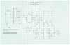
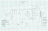
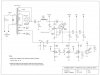
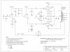
Keg -- The range of the various controls is as follows:
1. The cathode regulator has an adjustment range of about 5 volts, within the range of ~ 14 to 19 vdc as measured at point D. This voltage is adjusted by the EFB range control. Its setting is ultimately determined by the general bias voltage required by the particular output tubes used so that the bias controls themselves are adequately centered within their range when the correct quiescent bias is achieved for all four tubes. This set up is quite flexible, as to date I have not found any tubes that could not be properly bias with this design.
You may recognize that the circuit surrounding the 337 device is nearly identical to that which I originally published for the small Dynaco amplifiers a few years ago. Understand that the 337 circuit and associated adjustable positive bias controls were only necessary in my clone version, as the Fisher power transformer I used (from an X-101 ST) did not offer a convenient tap to facilitate a conventional negative bias supply. Therefore, the EFB cathode regulator version was used, with its attendant positive bias controls to effect an accurate setting. It also nicely chewed up a bit of excessive B+ I had as well.
In the actual Fisher SA-100 that I'm working on in a Fisher thread, traditional fixed bias is already employed, so an EFB supply regulator will be used instead -- also triggered off the screen circuit as the EFB cathode regulator is here. It will effect the same "Enhanced" action as the EFB cathode regulator does in my clone circuit, but does so by adjusting the negative bias voltage to the grids, rather than the positive voltage applied to the cathodes as done here.
2. The adjustment range of the bias controls is about 1.7 vdc, between a range of ~ 1.5 to 3.2 vdc. Looking at the voltages on the schematic then, with the cathodes at 15.25 vdc positive, and the grids at 1.4 volts positive, that has the tubes effectively operating with about 13.8 vdc of bias. With an effective 324 vdc applied to the screen, this 13.8 volts of effective bias allows the particular Gold Lion reissue tubes I am using to draw about 25 ma of quiescent current each.
3. The screen voltage control has an adjustment range of about 50 volts, within a range from about 310 to 360 vdc. Please remember that this project started life as a development mule, so the screen voltage was made adjustable to help verify certain performance characteristics.
In the end, the output stage basically operates under the same parameters outlined by RCA for 7189 tubes when delivering 24 watts (plate) power output. This requires 400 volts plate and 300 volts screen voltage -- or a screen voltage that is 75% of the plate voltage.
In my design, the quiescent plate B+ is effectively 432 volts, while the screens effectively operate at 324 volts. Note that this too is exactly a 75% relationship -- a relationship which is maintained throughout the full power range even though the main B+ sages some 50 volts from quiescent to full power output in both channels.
At full sustained power in both channels, the main B+ drops to 395 vdc, and the cathode voltage drops to ~ 13.5 vdc due to the Enhanced portion of EFB. This produces an effective plate voltage of ~ 382 vdc, and an effective screen voltage of ~ 287 vdc -- or again almost exactly 75% of the plate voltage.
Finally, note that a 50 volt drop in B+ means that the amplifier is operating on something over 88% of the original B+ value at full power output. Note too that at 13.5 volts on the cathodes under full power conditions, this is also an 88% drop in bias voltage from that applied under quiescent conditions.
In this way the complete operating parameters of the output stage are "slid" up and down as the main B+ is altered, but retain their original relationships in doing so as established under quiescent conditions. This is the very heart of what the Enhanced portion of EFB is all about.
This is quite unlike traditional installations, where in fixed bias designs the bias voltage virtually does not change at all as power output is elevated, or in resistive cathode bias designs, the bias actually goes up as power is increased. And, in traditional pentode circuits, the screen voltage typically falls quite rapidly with the application of power. With EFB II, because of the additional mosfet circuit, the screen voltage is unaltered by any increase in screen current itself, and is only affected -- always in proper proportion -- by a drop in the main B+ only.
By maintaining the various element relationships regardless of power output and main B+ levels, distortion is held to very low figures throughout the available power range. And, because the screen voltage is generally maintained at a higher level than typical resistive dropping networks allow for, available power output is increased as well.
The results produced by EFB and EFB II differ only in ultimate available power output from that produced by fully regulated voltages for each element. However, since both approaches effectively maintain the quiescent operating point throughout the available power output range, distortion is equally low with both approaches. But other than ultimate power output, both EFB and EFB II achieve virtually the same results otherwise as that of a fully regulated design with only a fraction of the complexity. It really is almost as good as having your cake and eating it too!
Dave