

You are using an out of date browser. It may not display this or other websites correctly.
You should upgrade or use an alternative browser.
You should upgrade or use an alternative browser.
Need Sansui 6060 Picture
- Thread starter archie2
- Start date
Register to hide this ad

archie2
Addicted Member
Sounds like a transistor is stuck on.
Rob
Could be but I don't see a transistor in that circuit. The stereo lamp is wired directly to the lamp board and the other leads to that board go to pins in the tuner board which have no visible resistors connected. I don't have the schematic so I'm eyeballing the boards. The stereo lamp leads look freshly soldered to the lamp board. If I had a picture of the lamp wiring I could tell if mine is right or wrong.

It looks like transistor TR15 turns on the stereo lamp. It is located on board F2590. It feeds pin 20 and one side of the lamp. The other side of the lamp goes to the lamp board.
So it could be the transistor or the chip that feeds it. You should be able to check it with a meter.
See schematic here.
Rob
So it could be the transistor or the chip that feeds it. You should be able to check it with a meter.
See schematic here.
Rob
archie2
Addicted Member
It looks like transistor TR15 turns on the stereo lamp. It is located on board F2590. It feeds pin 20 and one side of the lamp. The other side of the lamp goes to the lamp board.
So it could be the transistor or the chip that feeds it. You should be able to check it with a meter.
See schematic here.
Rob
Thanks. Cannot find TR15 on F2590, I have found R15 on the opposite side of the board from pin 20. Pin 20 has both leads wired to the light board. My stereo lamp also has both leads wired to the light board. So my stereo lamp wiring is incorrect.
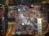
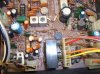
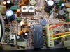

The transistor in question is to the left of pin 20 in the pic. Right in front of the white plug.
Looks like the AC for the dial lamps hits a diode and a cap to get DC on the F2651 board. One of those could be bad as well. Pin 20 on the other board looks like it goes neg when the transistor turns on. You can test for that at pin 20. If it does not change state, check the input of the transistor. It gets fed from the chip
through R49. Probably the chip right above it in the pic. R49 could be open.
Rob
Looks like the AC for the dial lamps hits a diode and a cap to get DC on the F2651 board. One of those could be bad as well. Pin 20 on the other board looks like it goes neg when the transistor turns on. You can test for that at pin 20. If it does not change state, check the input of the transistor. It gets fed from the chip
through R49. Probably the chip right above it in the pic. R49 could be open.
Rob
Last edited:

MY 990 was mod'ed for the lamps to stay on any source.Maybe thats it? Just say'n
Not the stereo lamp.
Rob
archie2
Addicted Member
I'm not sure I'm doing this right. On the schematic your finger is pointing to R62, a 100K resistor. But you said TR15 was right in front of the white plug. When I test TR15 on pin 20 I get -0.00 regardless of the meter setting, power off. I'm not testing with power on until I get the test points right. So I'm a bit confused.
Edit: Dang, it would be nice if I read the right schematic. I was on the 5050, not 6060. I'll go back to the 6060.
Edit: Dang, it would be nice if I read the right schematic. I was on the 5050, not 6060. I'll go back to the 6060.
Last edited:
Whoops, that's not my finger.
I just pulled the schematic from the AK database.
If you meter from the lamp board where the stereo lamp is suppose to be wired (+), to pin 20 (-), when a stereo signal is received you should see voltage.
If it's there all the time, something is wrong.
Rob
I just pulled the schematic from the AK database.
If you meter from the lamp board where the stereo lamp is suppose to be wired (+), to pin 20 (-), when a stereo signal is received you should see voltage.
If it's there all the time, something is wrong.
Rob
archie2
Addicted Member
Whoops, that's not my finger.
I just pulled the schematic from the AK database.
If you meter from the lamp board where the stereo lamp is suppose to be wired (+), to pin 20 (-), when a stereo signal is received you should see voltage.
If it's there all the time, something is wrong.
Rob
Nope, I metered from TR15 to pin 20. Didn't think it was right. Metering from lamp(+) to pin 20(-) I read 4.6 VAC. Reading drops to zero when station is not in stereo or when I press the mono button.
Then the stereo lamp is wired wrong because it stays on when the meter reads zero and when the mono button is pressed.
It sounds like the switching circuit is working. I would expect to see at least 6 or 7 volts though.
See the capacitor on the schematic at the bottom of board F-2651?
The spot marked with a "g" near that cap is where the + of the lamp should go.
If you didn't, check from that point.
Your stereo lamp is definitely wired wrong.
Extend the leads and hook it up. Maybe it will work.
Rob
See the capacitor on the schematic at the bottom of board F-2651?
The spot marked with a "g" near that cap is where the + of the lamp should go.
If you didn't, check from that point.
Your stereo lamp is definitely wired wrong.
Extend the leads and hook it up. Maybe it will work.
Rob

JustinP
New Member
Probably a bit too late now, but this thread caught my attention. I have a 6060 and just recently opened it up to give it a good cleaning and all. Figured that while I have mine open, may as well take a glance over things and see if everything in your photos looks the same as in my receiver.
I can't say for certain, but it appears as if your stereo indicator lamp had been replaced at some time. I'd guess that since the wires look newer and sturdier than what I see in my system. As well, they were soldered back in the wrong location.
I don't have a photo readily available, but will get one ASAP. For now, I took your photo and edited in some little markings to show where mine is located at, which should be correct. Maybe someone can verify this?
Looking at the photo, negative (black) wire would be on the left.
I can't say for certain, but it appears as if your stereo indicator lamp had been replaced at some time. I'd guess that since the wires look newer and sturdier than what I see in my system. As well, they were soldered back in the wrong location.
I don't have a photo readily available, but will get one ASAP. For now, I took your photo and edited in some little markings to show where mine is located at, which should be correct. Maybe someone can verify this?
Looking at the photo, negative (black) wire would be on the left.


