

You are using an out of date browser. It may not display this or other websites correctly.
You should upgrade or use an alternative browser.
You should upgrade or use an alternative browser.
Pioneer SX-1980 80v Regulated Heatsink Preliminary Drawings
- Thread starter zebulon1
- Start date

Register to hide this ad

You have a sx-1980 to look at?
spit balling here..
Look at the vent hole position and what natural convection would do with the old heat sink.
IMO the FRONT of the heat sink where the transistors are mounted is a great big barrier to air flow. We'd want to minimize that.
Assume the easiest method of increasing lower to upper chassis air flow by raising the tuner board 10mm to 15mm with standoffs. Then the flow comes from that hole by the heat sink, through / between the transistors.
Enough of a square footing at the screw to support itself, say
So, we want to un restrict that airflow.
Some ideas:
Two heatsinks, identical?
the overhang is less on the "back" side next to the hole, OR lots of through hole area.
the longer part is over the rest of the board
your drawing, with through longitudinal slots turning it into fins, on both overhangs. Or perhaps a series of inline holes instead of slots to preserve strength?
Three or four parts, two are simple aluminum cubes, to mount the transistor, to the board and to mount the upper part(s) to it.
The upper(s) are either a flat plate, or an extruded fin assembly, (fins facing down?) with holes through the base metal in between the fins. Recess in fins that mates with block.
pulling in another post from yesterday:
spit balling here..
Look at the vent hole position and what natural convection would do with the old heat sink.
IMO the FRONT of the heat sink where the transistors are mounted is a great big barrier to air flow. We'd want to minimize that.
Assume the easiest method of increasing lower to upper chassis air flow by raising the tuner board 10mm to 15mm with standoffs. Then the flow comes from that hole by the heat sink, through / between the transistors.
Enough of a square footing at the screw to support itself, say
So, we want to un restrict that airflow.
Some ideas:
Two heatsinks, identical?
the overhang is less on the "back" side next to the hole, OR lots of through hole area.
the longer part is over the rest of the board
your drawing, with through longitudinal slots turning it into fins, on both overhangs. Or perhaps a series of inline holes instead of slots to preserve strength?
Three or four parts, two are simple aluminum cubes, to mount the transistor, to the board and to mount the upper part(s) to it.
The upper(s) are either a flat plate, or an extruded fin assembly, (fins facing down?) with holes through the base metal in between the fins. Recess in fins that mates with block.
pulling in another post from yesterday:
OK, I just spent some time looking at the SX-1980. Considering everything that everyone has posted.
That plate - if not carefully sized and positioned - will BLOCK the HUGE ventilation grid hole in the bottom plate directly below the 80v regulator's huge and ineffective heat sink.
MAYBE, an aluminum plate with a LOT of holes (easier to DIY than slots?) in it would even be better, considering:
The big vent grid in the bottom cover is ALREADY at least 35% BLOCKED by that huge hot heat sink, so Zeb, I see why you said that "cutting slots in the existing crappy heatsink would do wonders". Might even PUMP AIR IN as it got hotter.... lol...
Anybody adding a plate like shown above that comes ANYWHERE near the +/- 34v regulator heat sinks (you're pretty close!!! lol) should also electrically isolate those +/- 34v regulator power transistors from their heat sinks using mica and shoulder washers. You see, the +/- 34v pass transistor collectors (which make the heat sinks "live") are only 360 (r2) or 480 (r3) ohms away from +/-80v!! ZZAAAAAPPPPP.....
ETA: The heat burden of the current drawn from the +/- 34v supplies is imposed upon those +/-80v pass transistors.... hmmmm.... meditating upon increasing the wattage and resistance of R2 and R3 and run them over to the RAW 106v DC... just a thought...
NOW, the AIR that is getting IN those vents has to GO SOMEWHERE!!!
The through cabinet ventilation sucks. I suspect THAT is the choke point. The only deliberate air path seems to be gap between the AWE-093 pc board and the chassis. There are 6 fingers rising from the two brackets that are M3 tapped and mount the pc board,with six screws, and elevates it slightly already, leaving a three mm crack / vent between the bottom of the chassis and top of the chassis.
edit- there is an 8mm air gap between the tuner itself and the chassis hole that exposes the bottom of the tuner. More airflow potential than I expected.
The AWE-093 tuner assembly board has AT LEAST 30mm of clearance UP!!!
I'm looking into using 10mm to 15mm standoff spacers to RAISE the board, allowing more air to pass through.
In fact the 15mm male/female stainless or aluminum (HAS to be metal!!) M3 spacers I specified for relay mounting would be PERFECT!! ALL the electrical grounds the tuner board uses and NEEDS would only be lengthened 15mm.
With that type of space, IF natural convection isn't sufficient with modified heat sinks, a blower type fan could be put underneath it to blow air THROUGH that 10 to 15mm gap, but that adds a problem, there are two natural convection zones around the power amplifier driver circuit boards. We could starve them and overheat the drivers if we pull too much air from the other bottom plate vents. So it may be necessary to close off two air channels near the back corners of the unit, inhibiting the fan suction from reversing the convection flow through the bottom vents, across the amp driver cards and out the top. That's why I think a fan might be a whole can of worms...
edit - I "see" it in my mind's eye:
1. big aluminum plate mounted on top of the existing heat sink - with PLENTY OF HOLES.
2. insulated +/- 34v pass transistor heat sinks if that plate comes close...
3. RAISED AWE-093 board 15mm or more on standoffs.
4. IF necessary, one of those mini blowers that are 15mm thick can be put inside under the tuner card,
blowing through the gap between the chassis and the tuner card made by step 3...
Easy and reversible, leaving (almost, depending upon the aluminum plate mounting method) no trace
Last edited:

I understand what you are describing.
I think the two identical would be easier to make and be subsequently cheaper.
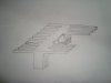
Here is what I was thinking about after dinner.
I'll work on the separate heatsink idea tonight.
Note; A little M.C. Escher in the design.

I think the two identical would be easier to make and be subsequently cheaper.
Here is what I was thinking about after dinner.
I'll work on the separate heatsink idea tonight.
Note; A little M.C. Escher in the design.
Attachments
Last edited:
The separate heatsink's would work for the the 13.5v regulator Q203. I just checked and that transistor gets cook'n hot as well.
Ok, FOUR blocks (identical). Big flat top plate with a gazillion holes.
Last edited:
And ------------ Q204! How could I forget!
Excellent! Four separate blocks all attached to a single top plate loaded with holes and connected with thermal-paste and machine screws. Hell you could stand on it. It would allow for easy access if needed.
Excellent! Four separate blocks all attached to a single top plate loaded with holes and connected with thermal-paste and machine screws. Hell you could stand on it. It would allow for easy access if needed.
Thermal design is a science in itself. So you want to pretend to be a thermal ME, since you axe'd the fan idea too 
Has anyone actually attached a tc on the hs and found out the op temp? This is your start point!
Attach to the area close to the hottest bjt on the hs. attach to each bjt body, plastic not live flange with tak-pak.
Since the HS is not live, then use the bottom plate as your heatsink extension.
How close is the existing HS to the bottom plate? Why did they not do this originally?
Steel is a bad hs material!
Modify the HS to fit between the existing HS and attach with metal screws, to the bottom plate.
Set a target end point op temp! for tc references.
While we are at it, modify the PS design to add over current & voltage control, too many reliability issues with this PS design. I submitted my first draft
Just joking, would never invest my time( unless I am getting paid) knowing that I do not own one nor want too. Now, if I had a transformer, then I could improve my test jig. I currently have a jig for a 1250/1050 and of similar size PA design.
See a error in the sch, no R(same as R239,13K) between pin 9 & 12, wire link on pcb assembly drwg, so why are the voltages diff?
have fun
Rick
Has anyone actually attached a tc on the hs and found out the op temp? This is your start point!
Attach to the area close to the hottest bjt on the hs. attach to each bjt body, plastic not live flange with tak-pak.
Since the HS is not live, then use the bottom plate as your heatsink extension.
How close is the existing HS to the bottom plate? Why did they not do this originally?
Steel is a bad hs material!
Modify the HS to fit between the existing HS and attach with metal screws, to the bottom plate.
Set a target end point op temp! for tc references.
While we are at it, modify the PS design to add over current & voltage control, too many reliability issues with this PS design. I submitted my first draft
Just joking, would never invest my time( unless I am getting paid) knowing that I do not own one nor want too. Now, if I had a transformer, then I could improve my test jig. I currently have a jig for a 1250/1050 and of similar size PA design.
See a error in the sch, no R(same as R239,13K) between pin 9 & 12, wire link on pcb assembly drwg, so why are the voltages diff?
have fun
Rick
Last edited:

I realize that this is a unscientific endeavor, but I do know that any idea based on the last 35 years of heatsink improvement would be better over the cheesy heatsink Pioneer designed. No extra moving parts and hopefully a 30 to 35 degree drop in transistor temperature. I more than any like to keep the OEM equipment. This mod can be reversed, returning the set to its original conformity. In a week or so I should have an idea of what this will cost. That's the potential game changer, not weather it will be a improvement over the stock configuration.
Keep this discussion going. Is it a waste of time?
EDIT: I did remember the caps "EW" uses and this is considered. A picture of the caps mounted would be a big help.
Keep this discussion going. Is it a waste of time?
EDIT: I did remember the caps "EW" uses and this is considered. A picture of the caps mounted would be a big help.
Last edited:

Two practices, one has the smaller radial caps close together with short grounds, and isn't as good for ventilation, and the other the caps have longer ground jumper wires, and are spaced far apart from each other.

I didn't want to waste the caps, but I am rethinking that board's cap placement
to like this, done a bit later:

I didn't want to waste the caps, but I am rethinking that board's cap placement
to like this, done a bit later:
Attachments


Last edited:
Thermal design is a science in itself. So you want to pretend to be a thermal ME, since you axe'd the fan idea too
<snip>
have fun
Rick
I will have fun, back in the 1980's in my checkered past, I was designing military equipment. There was a requirement for NO internal moving parts and the internal heat was eventually shed externally using thermoelectric coolers. (One effing miniature internal fan would have made life a lot easier) We shed the heat to the mounting brackets and then to the tank's turret. We had to do both convection and conduction to maintain a reasonable internal equipment temperature. It wasn't JUST me, but I made meaningful calculated contributions. (in fact once on that project, I had to BEG The VP of Engineering for two weeks straight to be allowed to take time off from it to help troubleshoot a seriously intractable production equipment problem that cropped up after PM - which I solved within an hour and made me the "steely-eyed missile man" of THAT company for a while, lol... The VP of engineering's jaw dropped and he asked "WHAT THE HELL" (he normally NEVER swore) "DID YOU DO?????" He'd been PERSONALLY spearheading the effort for those last two weeks and he was the guy who I had to beg to green light my involvement. He was also one of the sharpest engineers I have ever met. THAT was one of the BEST times of my life....)
And YES, the military equipment functioned and we quite happily turned some old surplus equipment on the range into scrap metal ("through the dot").
Disclaimer - I WASN'T there to do it... It wasn't a test if the engineers could do it, but rather if soldiers could use it effectively.
The adage was, "when the SHTF, it's 3rd graders that are operating it".
Of course, NOW, It's hopelessly outdated...
Didn't axe the fan idea, just articulated some unintended consequences that would have to be dealt with.
Last edited:
SolderIron
Addicted Member
Breaking an egg or two to get an omelet.
On equipment I want to keep, I move the hot power supply trans to a good heat sink. The chassis turns out adequate in most cases.
On equipment I want to keep, I move the hot power supply trans to a good heat sink. The chassis turns out adequate in most cases.

I mount the two caps vertically, at the far left edge (looking from the back of the unit), away from the heatsink. One of the cap leads has to be lengthened, but no biggie.I didn't want to waste the caps, but I am rethinking that board's cap placement
to like this, done a bit later
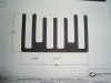
I was looking at a better heatsink extrusion that’s already available and I found this one. The height is perfect for adding the additional cooling plate. I thought I would order something like this example. The dimensions for the existing space on the board will allow for a larger heatsink foot print on Q203, Q204 by 20% plus you will get a deeper and taller HS profile.
The HS’s for Q208 and Q213 can be quite large as there is some real estate on the board in that area. Offsetting the HS will make a pretty good standard HS with clearance for other components in the area.
The supplier is flexible and I think I will order enough to make one set (Of four) and try out the HS just by themselves. Take temp measurements and see what effect of change happens by just replacing the original ones.
By the way; the remote resistors R2 and R3 can burn!

The HS’s for Q208 and Q213 can be quite large as there is some real estate on the board in that area. Offsetting the HS will make a pretty good standard HS with clearance for other components in the area.
The supplier is flexible and I think I will order enough to make one set (Of four) and try out the HS just by themselves. Take temp measurements and see what effect of change happens by just replacing the original ones.
By the way; the remote resistors R2 and R3 can burn!
Attachments
Wow!! that seems to be a tall order and not even knowing what the op temps are currently at = unscientific to say the least.No extra moving parts and hopefully a 30 to 35 degree drop in transistor temperature.
It is funny to hear something being of more value, when you know it is poorly designed, has reliability issues, left original and of less value if it is properly modified. Logic would tell you otherwise but the world is a weird place. As soon as you change one comp from what was org spec'd, it is not original anymore. I use the 2sk34 ccs mod as an example.
Of course, it is a worth while exercise, if it improves reliability.
The more I look at the design, I see poor choices, like they could have provided two more taps on the transformer secondary for a lower voltage and not need the huge amount of power dropped by R2,3(10w R's). Crazy when you think that the supply dissipates as much or more power than the load does. I'd have to do the math to figure out the efficiency of this PS design, but it does not look very good, no wonder their are PS reliability issues.
Actually, they could have saved one tap, raise the V for the green wires (for the +/-34V supplies) and add one more tap for the lower voltages,13.5,8,5V. A half wave rectifier would work fine.
It is a custom designed transformer with only use for one model!! More wow factor, oh well water under the bridge as they say, listening to blues puts my mind in this state, what can I say, time for some wacky

As always have fun.
Cheers
Rick
Last edited:
Wow, you've been a real a ray of sunshine recently. Who rained on your parade?
Lighten up on an enthusiastic ex-noob.
I give the guy kudo's for coming up with the antenna mount replacement, and figure the detractors (I've seen a few barbed comments in eBay listings where they have doubled the price of originals, saying they are the REAL parts) are just sour grapes. I am loosing respect for them. You sound like one of them, at least to me.
And that is with the FULL disclosure that I was working on an antenna mount fix too, and could have been considered a potential competitor. As it stands I am OVERJOYED a viable fix is available, and happily discontinued my efforts in that vein.
As it is there are MANY non-Pioneer units whose deficiencies, foibles, quirks and failures are well known, and compensated for in the freshening process, to whatever degree it is done.
"Let he who is without sin cast the first stone".
OH and for this:
We DO know the temperature, sitting open on the bench, and what happened with a approx 6 x 6 metal plate just clamped on with thermal grease
then there's this, and while it doesn't explicitly SAY 88 degrees F in the text, the picture folling it speaks volumes:

and... I am almost at the point with clearing the bench for this action where I can recreate all those tests.
Lighten up on an enthusiastic ex-noob.
I give the guy kudo's for coming up with the antenna mount replacement, and figure the detractors (I've seen a few barbed comments in eBay listings where they have doubled the price of originals, saying they are the REAL parts) are just sour grapes. I am loosing respect for them. You sound like one of them, at least to me.
And that is with the FULL disclosure that I was working on an antenna mount fix too, and could have been considered a potential competitor. As it stands I am OVERJOYED a viable fix is available, and happily discontinued my efforts in that vein.
As it is there are MANY non-Pioneer units whose deficiencies, foibles, quirks and failures are well known, and compensated for in the freshening process, to whatever degree it is done.
"Let he who is without sin cast the first stone".
OH and for this:
No extra moving parts and hopefully a 30 to 35 degree drop in transistor temperature.
Wow!! that seems to be a tall order and not even knowing what the op temps are currently at = unscientific to say the least.
We DO know the temperature, sitting open on the bench, and what happened with a approx 6 x 6 metal plate just clamped on with thermal grease
170 degrees F. It doesn't take long to get there, a few minutes is all. You can keep your finger on it for about two seconds.
then there's this, and while it doesn't explicitly SAY 88 degrees F in the text, the picture folling it speaks volumes:
Well well well....
I pulled R212 that measured 6.8ohm and put in one that measured 5.7, still blazing hot heat sink at about 180deg. After staring at my voltage readings until I had a headache pulled the D213 17/18 volt zener combo and put two new ones in. The output voltages on the negative side went up about a volt. Heat sink still too damn hot. okokokokok, I give in, reinvent the wheel, added a steel plate and ...TADAAAAA, this pic is after a 20 minute mid volume run.
edit... 2 hours and still going well
and... I am almost at the point with clearing the bench for this action where I can recreate all those tests.
Last edited:
Overund1, i see the zener Service Bulletin incorporated. Did you do the mod "Echo Wars" suggests with the radial caps? If so, a image of that part of the board. Thanks
ZEB:
LOOK at Hogwild's picture one post up, look at the lower portion of that shrouding metal plate, there are two radial 'lytics standing up inboard of the 4 fuse group, and parallel to that fifth, illumination fuse.
Look like UPW's, upright....


