• The move to the new server is done. There are some software and database maintenance updates in process. This has us passing the hat around to help out. We appreciate any donations. Seriously, even a dollar helps. The payment page may be found here - https://www.audiokarma.org/support.html

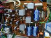
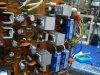
Pioneer SX-1980 80v Regulated Heatsink Preliminary Drawings

Good test results!!

I can see an aluminum plate that fastens to the steel h/s used for the +/-80V regs and extends to the position where the 13.5, 8V pass bjts reside(Q201,205), having a 90 degree bend. Use shoulder washers, mica insulators to mount 13.5, 8V pass bjts, 4-40 machine screw threads into the aluminum angle plate.
Is there enough clearance over the ecaps sitting in the middle?
If there is clearance between the new h/s and the bottom plate, could add extra rectangular omni-directional H/S, like the ones used for BGA/PQFP packages, they come in various fin heights.
 
Last edited:
>They topped out at 190.1 F., after 10 minutes. The original Pioneer duel heatsink for the +- 80v regulators Q210 and Q211 topped out at 151.1F.

What should be the objective temperature? Keeping in mind the junction temperature spec with margin (25%??), hottest room temperature in summer, and some what restrcited air flow.
 
I was hoping a member would interpret the numbers.
http://www.mouser.com/ds/2/308/MJE15032-D-95003.pdf

The outside temp was 83.4F (28.3C)

The 150.0F (65.1C) on the duel seemed OK. The 190.0F (87.7C)seemed hot. If the new larger (shown above) heatsinks help cool it down with hardly any modification; It may end there.

MTF was also discussing a spacer between the tuner board to lift it up, gaining better venting to the top of the set. This would be noninvasive as well.

I won't start on that heatsink replacement until this next weekend. It shouldn't take long once I get past messing with my really nice (perfectly functioning) set again.
 
Last edited:
If I am reading the specs right, the max operating range is: max temp (87.7C) minus OAT (28.3C). The data indicates a 60.0C difference. which is right at the limit for the MJE15032's.
 
Last edited:
The exercise is to determine the junction temperature. Obviously it must be less than the maximum stated in the data sheet.
You need to know the device power dissipation, this should be easy enough to figure out. Then work towards determining the device junction temp by factoring in the thermal gradients, theta jc(package), theta cs(mica). Once known, you can then predict the component reliability. The most basic rule is, when you half the junction temp, you double the components life. The goal is to reduce the junction temp to meet your reliability target. It is probability.
 
Using the PIOOMA method and with ancient knowledge of production test temperature being 140 F, a rough target is less than 140 F on the HS in the hotest day. PIOOMA was used long time ago and it means " Pull it out of my ___".
 
Zebulon1
Doing the temp measurements on the original heat sinks for the 13.5v regulator Q203 and the 8v Q205. They topped out at 190.1 F., after 10 minutes.

The original Pioneer duel heatsink for the +- 80v regulators Q210 and Q215 topped out at 151.1F.

I installed the new profile heatsinks on each of the hot transistors: Q203 (13.5v), Q205 (9.2v), Q210 (80.6v) and Q215 (-80.6).

Outside air temp 75.5 F
Readings in Fahrenheit
The -+ 80.6 volt regulators (Q210, Q215) get to 161.5 each.
The +13.5 volt regulator (Q203) tops at 178.1.
The 9.2 volt (Q205) gets to 151.2.

attachment.php


attachment.php


attachment.php


attachment.php


attachment.php


Conclusion:
The +- 80.6 volt regulators run 20 degrees hotter considering the outside air temp.
The smaller 9.2 volt regulator benefited from the larger HS, gaining the most by cooling down almost 30 degrees. The 13.5 dropped only a degree or two. Note: the OAT (Outside Air Temp) is 10 degrees cooler than on the original heatsink test (The outside temp was 83.4F (28.3C) on 10-06-2014).
 

Attachments

  • 1980 hs mod 1.jpg
    1980 hs mod 1.jpg
    78.1 KB · Views: 198
  • 1980 hs mod 2.jpg
    1980 hs mod 2.jpg
    82.9 KB · Views: 92
  • 1980 hs mod 3.jpg
    1980 hs mod 3.jpg
    105.1 KB · Views: 97
  • 1980 hs mod 5.jpg
    1980 hs mod 5.jpg
    105.6 KB · Views: 98
  • 1980 hs mod 4.jpg
    1980 hs mod 4.jpg
    95.1 KB · Views: 196
Last edited:
Hey, I just realized a error I made in recording the temps. I had been taking the temps from the very backside (middle) of the heatsink, right at the inside base of the heatsink. This is only .18 inches from the transistor.

I am going to figure out a better point of measurement. I did notice the temperature does get hotter nearer to the transistor when first checking them with the original heatsinks.

This stands to reason: I had been touching them as I was taking the readings and they were cooler than with the orginial HS's. The 13.6 volt was the hottest at first and you could not keep your finger on it for over a few seconds. Now you can leave your finger on it.

I am sorry that I have been confusing you guys but I want to remain transparent (over used but fitting word) with my procedures.
 
Last edited:
How does the height of the installed heat sinks relate to the height of the relays?

Is there clearance?

My idea was very close to that, basically a plate that is screwed to the tops of the 4 (or 6?) heat sinks. If the plate shrouds the bottom cover's vent hole array, holes would be drilled in the plate as to not block the airflow, and perhaps even shed some heat in the airflow.

The only other idea bouncing around inside of my skull was to cut slots in between the fins almost to the to-220 outline, to free up some airflow restrictions.

These tests were conducted with the unit on it's side? And the bottom cover off?
 
There is room between the bottom cover and the top of the HS's, a hair over 1/4 inch.
Bottom Cover on with the set on the side.

I like the ideas but I need to find a better way to accurately measure the temps. They may not be needed.

I can say that the temps are cooler to the touch but no scientific data to back it up yet.
 
My first impression is that the HS fins should be rotated 90 degress, (fine if the unit is on its side but) the PS pcb is normally in the horizontal position, so the fins should be vertical. I know it won't make a whole lot of difference in this case because of restricted air flow, but heat does rise and HS data usually shows the Theta sa in both directions and vertical is always better, unless the HS is omni-directional, which is not the case here.
You have to have all the covers on, sitting in the regular position to get the right #'s, just to begin with.
Putting a t/c on a live HS is a hazard. If they are rtd's then you have to check isolation voltage.
For U/L testing, we used a bunch of "J" type t/c's and glued them on to isolated components, with Locktite "takpac". It has the glue and the accelerator, so it easy to do, but the stuff has an aweful stink to it and is rather costly, but that is cheap compared to getting the U/L EE in to verify your findings.
 
Maybe a dumb question but... No other transistor that can replace the Mje15032/33 that will work cooler?
 
rcs16, good tip on the adhesive. The tests are conducted in the same conditions. This was an attempt to see if any differences could be seen/noticed/measured. But like I said I am more confused now than I was at the start of this experiment. The confusion is more on measuring, accuracy and consistent data.

Another issue is using my set as a test bed. I signed up for this and will see it through but careful work is even more so as I'm in and out more than one time.
 
Maybe a dumb question but... No other transistor that can replace the Mje15032/33 that will work cooler?

The energy dissipation is a function of the CIRCUIT, not the transistor used. Quite frankly a ksa940 and ksc2073 would run EXACTLY as hot.

Temperature is a function of the energy input and the ability of the heat sink to transfer that energy to the air. The better it sheds heat, the lower the temperature rise above ambient temperature.

The mje15032/33 is used because they seem to tolerate higher junction temperatures better. This is from EchoWars's experience.
 
Need an engineers opinion on this one, just for the sake of argument:
My junction box cover plate, would cutting slots or drilling holes reduce surface area BUT help convection? Next 1980 that I get (I have one due in this week) I may experiment a bit.

Hoggy


then there's this, and while it doesn't explicitly SAY 88 degrees F in the text, the picture folling it speaks volumes:


and... I am almost at the point with clearing the bench for this action where I can recreate all those tests.
 
I have an older Fluke infrared temperature gun and will use it on the next check of the new stand-alone installed heatsinks. Should have a report by next weekend.
 
Back
Top Bottom