• Please note that Audiokarma will be offline briefly for updates early on Monday morning, September 28th.

10.7mhz tuning

Carbsandcaps

Super Member
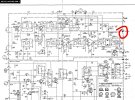
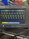
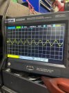
Working on this nightmare fisher 450tx receiver and I decided to try to align the tuner. I’ve got my signal generator set to 10.7mhz. Im getting pretty distorted output no matter how I adjust the 3 cans. How clean is this signal supposed to be coming out? Also the test point where you put the signal generator doesn’t actually touch anything so is this just acting acting as an antenna?
IMG_5120.jpeg
IMG_5122.jpegIMG_5067.jpegIMG_5123.jpeg
 
Register to hide this ad
I know nothing of that tuner but almost any adjustment of slugs requires that the signal be as small as you can possible deal with. If you're not down in the noise and muck, the signal is too large. See if that helps. Also, FWIW, I've never found an alignment procedure that's quite correct as written.
 
I know nothing of that tuner but almost any adjustment of slugs requires that the signal be as small as you can possible deal with. If you're not down in the noise and muck, the signal is too large. See if that helps. Also, FWIW, I've never found an alignment procedure that's quite correct as written.
Ya I had the generator down low but I couldn’t pick up anything with my scope. They’re talking about 100mv I have it turned up to 20v just to get a signal through but I don’t think that is accurate. That would make sense as to why it’s distorted
 
Wow, that's a lotta volts! Try reducing it so you can still see it, peak things, then reduce it some more. I don't know how much alignment you've done, probably more than me, but the things they never mention have to do with coupling into and out of the circuit. RF often needs to go in through a very small series capacitor, a couple pF or less. Sometimes outputs have to be treated the same way, lest the circuit be loaded down by the scope or meter. I've also found that sometimes RF has to be brought in through coax, with only the tiniest bit of the center conductor exposed. Otherwise, the poor shielding on consumer equipment allows the signal in at multiple locations, confusing the heck out of things. Then there are pads that supposedly either imitate the antenna or match the generator impedance to the input. Maybe those are the same thing, but they rarely give you the circuit. I guarantee the test bench at the factory and the procedure they used in production won't match the equipment at hand or necessarily be the best procedure for us to use.

The way TP 5J is drawn, it looks to be capacitively coupled to the transformer leg. If it weren't, it would have 14 V on it! It might be an actual cap or it might be proximity or it might be "gimmick" style, a wire with a turn or two around something else. That's why you can use a larger signal. I'd think tuning L505 would be straightforward and a good test case for knowing your setup is reasonable. I'm assuming a X10 probe on the scope, not X1!

 
Looks like the IF is completely overloaded. I use a Motorola R2670 service monitor at -46dbm and Tek 465 scope to align IF strips, inject the 10.7 at the output of the mixer and tune the cans for peak response on the scope to the 10.7 then zero the discriminator. After this I measure the voltage swing by going to 10.8 then down to 10.6 and look for symmetry in the output swing. Once complete I then drive in a on channel wideband FM at 100.1 MHz and modulate with a 19 KHz pilot at 10% no audio and look for birdies on the output terminals.
 
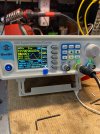
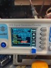
This is what I’m using. It’s a relatively cheap two channel with sweep function. For this part of the alignment it only calls for a wave generator. I’ve tried a capacitor on the leads with no change. I’ve also used it as an antenna with a capacitor and loop of wire and it picked that up. IMG_5066.jpeg
 
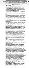
So I trust the signal generator has a clean sinewave coming from the output jack? No harmonics or other synthesized garbage and you're coupling into 5J with the ground on 5H? Are you driving in a full 6.0 volts of amplitude? That right there would be far more than enough to overload Q301 and Q302. SO what I would do in this case and this is just me is reduce the amplitude of the 10.7 signal going into 5J then with my 1x probe on my Tek 465 poke the base of Q301 and note the signal itself, it may not be a super clean waveform but that's not important at this step just adjust the top & bottom slugs of Z502 for the best amplitude at the base of Q301 then move on to the next stage and repeat with my scope probe on terminal 3 of Z504 looking for amplitude and noting how the waveform looks. The 10.7 does not have to be super clean however what I'm seeing in the image of your scope is clearly clipped and flat topping from the overload.

As much as I like The Fisher (Avery not Sanyo) they were always a little convoluted in service procedures and the manuals themselves a little lacking in details like stage gains & voltages. That being said I had a Fisher 800B as a teen in the early 80's and of all the receivers I've had over my 56 years this is the on I miss the most, I ended up trading it to a neighbor after my younger brother melted crayons over the 7591's and stunk up the house... dad made me get rid of it. The ironic part is I kept the 7591's and cleaned the crayon out and they survive today in my Magnavox Astro Sonic Imperial combo console that sports a Heathkit AA-100 amp in place of the original. I have done some extensive write-up's and journal my progress of restorations and "resto-mods" on the Ham Radio forum of smokstak.com in the blog "On The Bench". The internal receiver just lost it's remaining transistors in the audio path to a pair of 6DJ8's in a totem pole configuration. The receiver also got a full-on IF alignment and this is chronicled there as well.
 
So I trust the signal generator has a clean sinewave coming from the output jack? No harmonics or other synthesized garbage and you're coupling into 5J with the ground on 5H? Are you driving in a full 6.0 volts of amplitude? That right there would be far more than enough to overload Q301 and Q302. SO what I would do in this case and this is just me is reduce the amplitude of the 10.7 signal going into 5J then with my 1x probe on my Tek 465 poke the base of Q301 and note the signal itself, it may not be a super clean waveform but that's not important at this step just adjust the top & bottom slugs of Z502 for the best amplitude at the base of Q301 then move on to the next stage and repeat with my scope probe on terminal 3 of Z504 looking for amplitude and noting how the waveform looks. The 10.7 does not have to be super clean however what I'm seeing in the image of your scope is clearly clipped and flat topping from the overload.

As much as I like The Fisher (Avery not Sanyo) they were always a little convoluted in service procedures and the manuals themselves a little lacking in details like stage gains & voltages. That being said I had a Fisher 800B as a teen in the early 80's and of all the receivers I've had over my 56 years this is the on I miss the most, I ended up trading it to a neighbor after my younger brother melted crayons over the 7591's and stunk up the house... dad made me get rid of it. The ironic part is I kept the 7591's and cleaned the crayon out and they survive today in my Magnavox Astro Sonic Imperial combo console that sports a Heathkit AA-100 amp in place of the original. I have done some extensive write-up's and journal my progress of restorations and "resto-mods" on the Ham Radio forum of smokstak.com in the blog "On The Bench". The internal receiver just lost it's remaining transistors in the audio path to a pair of 6DJ8's in a totem pole configuration. The receiver also got a full-on IF alignment and this is chronicled there as well.
So that’s what I was wondering. It says send the signal through 5j then adjust all 3 cans at the same time to get the best signal out. I would much rather go step by step through it once can at a time but I wasn’t sure where the test point should be.
 
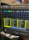
This is what I have directly at the scope
IMG_5148.jpegAnd this is what I have at the base of 301 and it’s not consistent at all it’s the same at the output of the fm front end which is just the other end of the wire going to 301 IMG_5150.jpegit feels like the signal isn’t jumping the gap
 
You are misunderstanding the calibration procedure. You have no modulation, therefore you won't see any audio signal at the output of the discriminator.
You can:
1. Connect your scope at the output of the limiter (the last IF amp) and
2. Reduce the output level of the signal generator until the 10.7MHz signal on the scope starts to drop in amplitude. Then the limiter is not limiting.
3. Tune the IF cans for max level on the scope.
4. Connect a DMM on DC volts to point 3M and adjust the top core of Z306 for 0V.
5. I need to figure out what test point to use to adjust the botttom core. I'll post later.
 
Normally with un-modulated signal you peak the IF using a meter on the ALC line, or if its got a signal meter you can use that. Its basically like doing an AM alignment. It won't give you optimal symmetry at all, it just peaks it for 10.7 mhz. Zeroing the discriminator is the second part of it. Its far from optimal but it will get you well within the neighborhood for a sweep alignment, or if its something that isn't all that great it may be plenty good enough for the job. This really does not work very well for FM stereo, and even with a halfway decent mono set you can hear distortion if its too far out of whack.

can also read out the 10.7mc on the scope but an analog meter works just as well and they are arguably easier to see a peak on. This is really the only thing I ever use my VTVM for. They also have a neat feature where you can set the needle to mid-scale for zero, which makes zeroing a discriminator super easy.

instructions above say to use a sweeper though, you should be getting the bell curve pattern if things are set up right, and on the discriminator you get that S shape.
 
When I started I was doing it by ear and with the signal meter there was a noticeable center point for each can but I couldn’t get any stereo signal at all. The generator does have a sweep option but I haven’t used it yet not sure if that would be considered modulation.
 
I believe you want to connect your meter to the + side of C335 and adjust the bottom core of Z306 for max DC voltage. I think when you are setting the level on the generator you can connect the scope to C329, the side that is not ground, and adjust the generator level until the 10MHz signal there starts to drop, then lower it a bit more so you don't push it into limiting if the level goes up from tuning the IF cans.
 
When I started I was doing it by ear and with the signal meter there was a noticeable center point for each can but I couldn’t get any stereo signal at all. The generator does have a sweep option but I haven’t used it yet not sure if that would be considered modulation.
If the generator has a sweep output to go to your horizontal input on your scope you could do it that way but it's a different procedure. Try it with the continuous signal first. Adjust the IF cans for max signal at C329, then adjust Z306.
 
The sweep is effectively frequency modulation since its changing it +/- from the center frequency.

anyway if you're peaking it by meter or the scope just make sure the signal output of the generator is low enough so it has a very sharp peak. Too high and you will have a range of adjustment where it tops out and doesn't change. Thats the limiter doing it's thing.
 
Not sure what the manual specifies for sweep width but if its say 1mhz, start it at 10.2 mhz and end at 11.2 mhz. 10.7 is right in the middle of those two points. If its 500khz, then go 10.450 to 10.950.

should also be a way to change the frequency. That might be the time value. Old ones often swept at 60hz simply because they used the mains input as the AC source to swing the frequency back and forth. If thats 20 seconds between min and max, you'll want to change that for sure.
 
Back
Top Bottom