• The move to the new server is done. There are some software and database maintenance updates in process. This has us passing the hat around to help out. We appreciate any donations. Seriously, even a dollar helps. The payment page may be found here - https://www.audiokarma.org/support.html

1060 - Purchased, now restoration

I am tempted to do just that. What gauge wiring should do? Where can i buy the standoff pins? Quick look on ebay and farnell have not yielded much, is there an official title for the standoffs?

 
Amp board completed, I put heat sink grease on 2 of the heatsink, I'm assuming no need for that as the heatsink might slip off? Probably the reason they were glued originally.

All transistors replaced, capacitors and one resistor.
 
I am kind of floundering to get this one finished, my time to get this over the line is very limited.
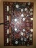
Whoever messed with the unit before me, left an awful mess on the circuit boards for me to fix, lots of burnt traces etc.
I bough some wire to connect the output transistors to the power amp board, far too stiff in my opinion i need something more flexible.
I foolishly also forgot to adequate detail that i would need a signal generator and oscilloscope to set everything up properly and finish commissioning!
Its a shame to have all the parts and then realise you blew your audio budget on a Onkyo A7090 with one dodgy channel!
 
I am kind of floundering to get this one finished, my time to get this over the line is very limited.
Whoever messed with the unit before me, left an awful mess on the circuit boards for me to fix, lots of burnt traces etc.
I bough some wire to connect the output transistors to the power amp board, far too stiff in my opinion i need something more flexible.
I foolishly also forgot to adequate detail that i would need a signal generator and oscilloscope to set everything up properly and finish commissioning!
Its a shame to have all the parts and then realise you blew your audio budget on a Onkyo A7090 with one dodgy channel!

I’m currently starting restoration on 2 1060’s. Lol yes I LOVE these amps. Although a scope is nice you can get away with setting the bias to 1/2 the Ps output. Usually 35v or so but I’ve seen some as low as 31v. It’s not exact but unless you have the volume level cranked to the max clipping shouldn’t be an issue. There are other threads that discuss setting it this way.
 
Instead of worrying about the trimpots (they are fine- good quality Alps units), replace your power switch if it is bad, also the switch suppression cap ::snip:::
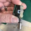
I would recommend you rebuild the power switch or at least take a look at it. I've got pics in a couple of threads here on how I've done it. Steady hands, a very slim flat bladed screw driver and a relay burnishing tool are all thats needed. I clean with DeOxit and then use their non-conductive grease that has DeOxit in it to lube the contacts.

Most time you can save the switch. Most.. sometimes it's cooked but you don't know till you take it apart.

Here are two sample pics from a 2226B power switch. It's been pretty much the same for the 2285B, 2226B, 1030 and the 2230. Your milage may vary :)
 

Attachments

  • IMG_2383.jpg
    IMG_2383.jpg
    49.6 KB · Views: 62
  • IMG_2387.jpg
    IMG_2387.jpg
    55 KB · Views: 61
I am still no further along with this project i am ashamed to say.
Just really need to get this up and running - hardest part is almost done with the power amp board, just need to solder a few bits up and then test.
 
No need to be ashamed. I'm finally back to work on my 1060 after more than a few months. I had a few other DIY builds, preamp, Class A amps, speakers, and a Sansui AU-717 rebuild, get in the way. ;) Good luck on getting your 1060 up and running!
 
Really not happy with some of my soldering on this, specifically connecting wires to the boards, from outputs to board and then on the big caps. Its like I need three hands. All solder joints are mechanically fixed well etc, I use flux and good quality solder and decent heat. They end up not looking shiny. Doing caps and smaller transistors on boards seems so easy. Anyone have this issue? If so how does one overcome this?
 
All solder joints are mechanically fixed well etc, I use flux and good quality solder and decent heat. They end up not looking shiny.
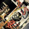
What I do is using stainless tweezers, I remove the wires by lifting straight up after heating the joint. I then straighten out the joint using heat and needle nose if needed. I then use heat shrink to "sleeve" the end of the wire about 2 inches back in the color of the OEM wire or I use clear. The heat shrink takes the abuse of the re-soldering whereas the OEM vinyl wire goes to **** when you heat it. This lets me put a nice wrap and decent heat to get a clean joint. On the caps, I use eye rings that I have crimped and soldered into place before attaching the wires back to the caps. Here is a shot of the cap with the eye ring before I finish attaching wires
IMG_4258.jpg
 
First magic smoke - Dimbulb tester bulb - check before you test.
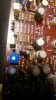
F*** My Life. R746 R726 R735 up in smoke, who knows what other harm i have done
 
Where do i go from here?
I have no idea where to start -
Do i pull the outputs and test?
Check orientation of the transistors is correct?
I am pretty much assuming i messed up one side of this board completely?

Calling any and all help, thanks in advance
 
.
 

Attachments

  • 15404038374204288462913446471820.jpg
    15404038374204288462913446471820.jpg
    50.7 KB · Views: 32
  • 15404038627063387637369890799091.jpg
    15404038627063387637369890799091.jpg
    37.1 KB · Views: 33
Back
Top Bottom