Follow along with the video below to see how to install our site as a web app on your home screen.
Note: This feature may not be available in some browsers.
The move to the new server is done. There are some software and database maintenance updates in process. This has us passing the hat around to help out. We appreciate any donations. Seriously, even a dollar helps. The payment page may be found here - https://www.audiokarma.org/support.html
Just to try and put a clear message on the replacement transistors for the Power amp board in Marantz 1060.
It would be nice if someone can confirm these as correct so that anyone who comes after will have another reference
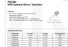
H706,H705 Replace with KSC945CGBU - Different Pinout than normal - (C Suffix)
H708 and H707 Replace with KSA733CGBU - Different Pinout than normal - (C Suffix)
H710, H709, H704, H703 Replace with 2N3440 -
H711 and H712 Replace 2N5416
H701 and H702 Replace with KSC945CGBU Different Pinout than normal - (C Suffix)
I'm not that knowledgeable about transistors, but it seems that I see more references around the forum to KSC945CYTA and KSA733CYTA. I looked at the data sheet, and all seem to have the same operational parameters. The only difference I can see is the packing method. Hopefully someone here can tell us the difference and if it matters in application.
I might well be wrong also, seriously, who am I to be dispensing advice. I think it is only the C part that matters, the transistor is the same, but the pinout configuration is different. Hence why I had to cross some legs.
Open to any correction on this obviously.
Ok i have to replace the 18 ohm resistors attached to H713 and H714.
The didoes read 0.9v each when checked with meter - Can anyone confirm this is correct?
I though diodes were supposed to be between 0.4 and 0.7v when checked?
I changed pretty much all the resistors on the board - checking each of them to see if any were damaged in the magic smoke fiasco, so i thought i would just replace them as i went along.
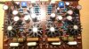
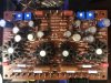
Nice progress Paul. I believe the old H713-H714 were thermistors with a resistor attached. This was a factory service item at the time. Now, these can be replaced with a 1n4148 or 1n4448 diode. No resistor needed and they don't need to be attached to the heatsinks of the driver transistors. You can see them on my re-build below.
Also, going back a few posts, yes your list in post #85 is correct to the best of my knowledge. And as you found out the hard way, the C suffix makes a big difference! Hope you got those crisscrossed legs all nicely insulated.
Bump, Can someone direct me please, going to reinstall the original pots, I've got a 470k pot on the board instead of a 470 pot!! I have got me a lot to learn folks, what a mistake, yet another in a litany.
Would that cause the bias to jump around like crazy? i could not get it to settle at all really.
I did not think that the wrong value pot would cause the jumping around and not settling on a value, either way i have to remedy this.
Which leg points towards center of the board?
I do not really get how to figure out which leg is the wiper and where said wiper pin goes.
Generally, the pin that looks like the center is the wiper. You should be able to test with an ohmeter. Check resistance between two terminals. If neither is the wiper, the resistance should not change when you turn the shaft. If either is the wiper, it will change.