• The move to the new server is done. There are some software and database maintenance updates in process. This has us passing the hat around to help out. We appreciate any donations. Seriously, even a dollar helps. The payment page may be found here - https://www.audiokarma.org/support.html

1964 Fisher Ambassador

racfan9

Super Member
Good Evening All,
I've posted a lot on AK over the past few years but never in the Fisher Forum but since I've acquired two Fisher Consoles in the last three weeks I figured I needed to make the move. Anyway a couple of weeks ago I picked up a 67 Fisher Diplomat lowboy style and this past Saturday I picked up a 64 Ambassador that is absolutely gorgeous. My questions tonight involves the Ambassador and the 69a amp and the 69t tuner. When I picked it up they had it powered up but told me they weren't able to get any sound out of it. Since it was already on I went a head and tried a few different things, I had taken a rca to mini jack to play music from my phone. I tried both inputs Aux and tape but nothing, radio was completely silent and no noise from the record player. I also messed with the speaker switch thinking there could be a problem there but still nothing. I shut it off after that, although I didn't smell anything odd and nothing seemed hot. So I paided $75 she originally wanted $200. So were should I start as far as trouble shooting? I have only found one fuse on the amp and it is fine, I checked all the output tubes and the 12AX7's and there fine. Oh I did hook the cabinet speakers up to a small Realistic receiver and they sounded great, so it's not a speaker problem. Anyway I was hoping it would be a simple issue but that's not looking very promising now. Any help would much appreciated. I have very little knowledge on electronics I can replace caps and resistors but trouble shooting is my big issue. Hope someone can help.

Thanks,
racfan9
 
Register to hide this ad
Are the amp and tuner separate components? Could it be as simple as the two being disconnected? I would expect some type of DIN plug connector somewhere....
 
No, Everything is connected. Amp powers on as does the tuner. I've also disconnected the rca's from the tuner to the amp and plugged my phone via rca to mini plug into the amp but still nothing. I'm really hoping my transistors are not blown but I'm starting to think the worst. Is there more than one fuse in the amp?
 
1ST things 1ST. Nomenclature. The model # of the '64 Ambassador is the A-69, the tuner model is 690-T, and the amp is 690-A. The Tuner and amp are separate as in they are connected via RCA Cables for signal from the preamp to the amp, and a wiring harness from one to the other for power and lighting. This was the 1st year FISHER was putting Solid State parts in their gear. The 690-a and 690-T were renamed the 59-A
for the Amp(which didn't change,) and the 59-T which changed slightly(mainly layout and changing the swithes from 1 rotary to 8 push-push switches.) Both the 64 and 65 variants were used in the Futura and Ambassador models, in addition to the '64 Statesman (S-79). 1966 the internals changed to a 1 piece chassis which was all Solid State except for 3 nuvistors in the Tuner Front end.

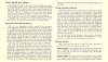
2nd. Make sure that the AUTO-OFF FEATURE is in the OFF position. Leaving it in the ON position will make it appear that the unit is on but will not work unless the phono is engaged. The following is from the F-59 FUTURA which uses the same Tuner/amp combo. This is from the Operating instructions and also has the tube layout drawings.

ScreenHunter_286 Mar. 22 11.32.jpg


Download OPERATING MANUAL and print out.
http://www.fisherconsoles.com/owners manuals/fisher futura v om.pdf

Download the Service manual and print it out.
http://www.fisherconsoles.com/service manuals/fisher ambassador a69wa sm.pdf


As the amp has tube drivers, and transistor finals it's considered a Hybrid amp. The tuner and preamp is all one unit and is all tube powered.

There is a MAIN 3A fuse on the Amp(F5) and 4 2A fuses (F1 thru F4) in the area of the speaker plugs on the amp. Use standard AGC 250V rated fuses. 120v rated fuses are right at the ragged edge with today's wall voltage. Can be had at Home Depot/Lowes/Ace Hardware/etc. BUSS and Littlefuse are very good fuses.

The plugs from the amp to the preamp sometimes lose connectivity. Reset them after spraying with short spurt of DeOxit D-5. Clean and check with Ohmmeter all of the fuses.

The amp is NOT designed to run separately unless it has been modified for individual use. A couple of things you can do to test each section. you will leave the main wiring harnesses connected but disconnect the RCA cables.

clean all of the tuner/preamp and the amplifier tube pins and sockets with DeOxit and a small brush, and for the sockets a dental braces brush. Use a jewelers small flat bladed screwdriver to tighten the socket leaf's.

Access to a tube tester is highly recommended. A gm meter is desirable but an emissions tester will do just fine for what you need to do now. Test all the tubes for GO-NOGO condition (GOOD-WEAK-BAD). Mark each tube with the position it came out of. Mark each tube with it's "V" Number. Take out and test, replace in it's original socket. Write down the results.

If you have a separate preamp and a tuner, connect the output's from the separate preamp to the 69-A inputs and test the amp. If it works you have a problem in the Tuner/preamp.

Then test the tuner/preamp with a separate amp by connecting the RCA's from the 690-T output's to the inputs of the amp.

Summary; At 1st glance it almost sounds like the Auto-OFF is in the ON position. If the unit is in the PHONO position, and the turntable is on, the whole unit is on. When the turntable shuts down after the last record, it shuts off the whole unit.

Clean all of the pots and switches on the Tuner chassis. There may be 4 pots on the amplifier. DO NOT TOUCH these 4 pots or the amp is guaranteed to burn up. They govern the output bias, and are highly sensitive, and the procedure must be followed with the required test equipment.

Clean all the tubes pins and sockets, all switches and pots. Check Fuses with an ohmmeter. Visual inspections pickup less than 1/2 of bad fuses. DeOxit the Wiring Harness connections and work them in and out a few times to scrub the contacts.

Check the Auto Off knob and put it in OFF position. Test. remember it takes about 30 seconds for it to warm up enough to start making sound.

Do the separate unit tests with other preamps and amps.

Test all tubes for GO-NOGO condition. None of them need close matching either between sides (L&R) or between sections (12ax7's).
This will get you started.
 
Thanks Larry for the info. I have checked the auto off switch, I've switched it back and forth a few times but it's extremely stiff. I haven't cleaned it yet but plan on doing it tonight after work. As far as the fuses I didn't see the 4 that are near the speaker connectors so I'll check them tonight also. And last to test the amp separately what wires would I jump to power it on? Thanks again

racfan9
 
All wiring harnesses and RCA's made up from the tuner/preamp to the amp. Now pull the RCA's from the output's of the Tuner (from the tuner to the amplifier) and connect them to the separate signal source (preamp, Cd player or tape deck with volume control). Turn on everything and see if the amp works. The Auto-Off switch will either have to be bypassed or cleaned so it works 1st.

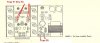
If the fuse caps(F1 thru F4) are missing, you won't be able to test/run the amp. You will be able to test the preamp/tuner. If they are missing, let me know I might have some on a spare 59-A. I'll have to check in the shed. Fuse F1 thru F4 are strictly power fuses to the amp B+. They have nothing with powering up the tuner/preamp. If F5 is intact, you can power up the tuner/preamp, and using the same RCA's disconnected before, disconnect at the amp, reconnect at the input from the tuner. The free end will go to the separate amp. The 690A- & 690-T wire harnesses must be connected.


ScreenHunter_287 Mar. 22 14.47.jpg
 
Good Morning, Larry I did a quick check of the auto off switch last night still nothing. I tried removing the four fuses on the amp but I couldn't get them out, is there a special trick in removing them, I pushed them in and tried to turn counter clockwise but they wouldn't budge.

racfan9
 
Mine unscrew. Standard thread.

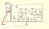
One more thing you might check is the REV-OUT / REV IN JACKS . If there is no jumper in them the unit will not sound off. If jumpers are missing double ended RCA Cable (as short as you can get or make) will work in it's place. These jacks are on the back side of the tuner chassis . If they are there make sure they are not pushed in so hard they are making contact on the ground of the jack. (outer part is ground). Pull out partway to clear ground contact.

ScreenHunter_288 Mar. 23 15.29.jpg
 
Last edited:
Hey Larry, Checked the jumpers on the tuner and they were ok. Hooked up a solid state amp out of a Packard Bell console in place of the Fisher and got nothing. Now this particular PB amp has the speaker inputs on it. Then I ran the Fisher amp into a Nikko1014 in place or the Fisher turner and still nothing. I don't have much hair left but what I have I'm about ready to pull it out. I have noticed that there is some noise in the speakers since I've started doing all these test. It's kinda like thunder in the distance and mainly out of the right speaker. I know where I can get another 690-A that is suppose to be in good working order but I hate to fork out another $300 although he guaranteed it, for something that might not be the problem.

I also have yet to get the four fuses out. The manual says to push in and turn counterclockwise, I just can't break them loose and I'm afraid I'm going to break one of them.

Thanks
Terry
 
Terry -- Can you come out of the "To Power Amplifier" jacks on the tuner/preamp to a different amplifier/speaker combination and get sound? That would at least verify if the tuner/preamp is working, or (part of) the problem. Although remember that the tuner/preamp receives all of its operating power from the power amplifier chassis power supply. Therefore, if the tuner/preamp does not work in this test, it may still be something in the power supply on the power amp chassis that is not letting it work, rather than the tuner/preamp itself. For the record, the tuner/preamp unit is quite dependable, so the great odds are that the problem will lie in the power amplifier chassis.

Dave
 
Dave, Yes that was one of my test I did last night. I've got a Nikko 1014 receiver with a bad amp section along with a solid state amp that was a console pull out of a Packard Bell. I've actually been using that setup in my garage. So I simply disconnected the rca's from the Nikko and ran them to the Fisher amp leaving everything in the Fisher amp and Fisher tuner plugged together and got nothing but hum through my garage speakers. My second test was to disconnect the rca's at the Fisher amp and plug them into the PB amp to see if the Fisher tuner would control the PB amp, but again nothing.

Terry
 
OK. Test tubes of course, but I'd be going after both the high AND low voltage sections of the power supply in the power amp chassis. For example, the 12AX7s in the audio section (i.e., not in the MPX section) are usually heated by DC power from the power supply. If the heaters are not receiving any power however, then there will be no output from the tuner section, as surely as if the B+ to that chassis were dead as well.

Dave
 
Hey Dave, May be a stupid question, but would the tubes still glow if the heaters weren't receiving DC power?

Terry
 
Only if they were AC Heaters. On the FISHER 690-A You have AC heated tubes and DC Heated tubes. AC Heated tubes are V201-V202-V203(AMP), (2 mpx tubes which are also marked V1 & V2 on schematic) and V1 thru V9 (Tuner). DC Heated tubes are V10-thru V13(preamp section). All of the AC Heaters are broken up into 2 different circuits. I agree with Dave. You've got problems in the POWER SUPPLY section of the amp, which also supplies the preamp/tuner.

A lot of times the fuse holder caps fuse to the holder due to dust, contaminants and moisture. The contacts inside can corrode, or rust. Hit them with a little PB Blaster on the seam of the cap to holder, then let sit overnight. Push down HARD and Twist to the LEFT(counterclockwise). It won't be much of a twist, and it may not pop up by itself so you'll have to help it along. But it should eventually come up and off.

Take and clean the pins on the tubes with a small brass brush and DeOxit, along with cleaning the tubes socket holes with Dental Brace brushes and DeOxit. Make sure all the pins are tight in the sockets. The distant Thunder sounds like a tube or two are making intermittent contact. You're primary problem right now is getting the power supply back to snuff, so everything is getting good clean voltage.
 
Last edited:
Not a stupid question! The answer is yes, and no. All of the tubes in the MPX sub-chassis, and the tubes in the "radio" portion (i.e., the RF tuner chassis and the IF tubes) WILL glow, because the heaters in these tubes are all powered by AC power taken directly from a winding in the power transformer. All of these tubes will no doubt be glowing -- as long as the heater elements in those tubes are good of course. The particular tubes in question will be four 12AX7s two of which will certainly have shields over them, and the other two may or may not. None of these will be on the MPX sub-chassis.

I just looked at the schematic -- these four 12AX7s are all powered off the same DC power supply that supplies power to the SS power amplifier section as well. Therefore, they can be used as a great troubleshooting indicator. However, these tubes are all connected in series: If the heater in one tube goes out, then none of them will light. Therefore, first make sure that these tubes are all good. Then, with them known to be good, if they do not light -- or light very dimly -- then the DC power supply in the power amp section will definitely need attention, and likely will be the reason that both the power amplifier chassis, and the tuner chassis are dead.

Dave

Edit: Looks like Larry covered this well!
 
Thanks Dave and Larry, You guys are such a help. I did cave and bought that other 690 amp I had mentioned earlier. So I guess i'll have a backup if I can get this one working. Thanks again.

Terry
 
Finally I got the 4 fuses out, and yes I was going about it the wrong way I though the hex shape nut is what was turned counterclockwise not the fuse itself, and by the way they were all good.Next thing, I've got a schematic of the amp and tuner but there very light and not very many voltage readings. So with that being said I've got a couple questions. First, what should be the voltage to the heaters on the 12AX7's? Second, What pin number supplies power to the tuner and my last one for tonight, do I need to leave all the tubes in while checking voltages?

Terry
 
Question #3. Yes
Question #2. You need to look at the power supply and follow the leads out from the rectifier, most will go thru the 12 pin rectangle on the schematic (the molex connector). It's numbered and you'll need a magnifier to see the numbers. Pins 1-5-9-10-11-12 are for the tuner and Preamp B+. Start at the power supply on the amp schematic as everything comes off there. Study the schematic and the amplifier and correlate the schematic to individual parts on the amp chassis'. Once you are comfortable doing this, you can mark certain wires or can caps, etc., underneath to help you.

Question 1; Pins 11 & 12 on the 12pin Molex Connector are for the 4 12ax7 heaters and part of the tuner. It's a 24V AC circuit, with the tube heaters in series, so they are wired for 6V heaters. 5.8 to 6.2v is good.

Sounds like your printer is set for economy printing (which scrimps on ink usage). Change your settings on the printer dialog box, or save the file on a flash card/chip and ask Office Depot to enlarge and print it out. I find that printing out the schematics at 200%-300% helps understand the undersides of the chassis. And well worth it. If they have a printer / plotter you can have it made on a poster sheet.
 
Thanks Larry.. Has anyone on here come up with a kit for the filter caps? If not is there any values I should change or just stay with the factory specs. The two black can type cardboard caps 3000uf 35v, should they be left alone? I'll start checking voltages over the weekend and get back with everyone Sunday evening.

Terry
 
Back
Top Bottom