• The move to the new server is done. There are some software and database maintenance updates in process. This has us passing the hat around to help out. We appreciate any donations. Seriously, even a dollar helps. The payment page may be found here - https://www.audiokarma.org/support.html

1964 Fisher Ambassador

Thanks for the guidance Larry, I haven't taken anymore voltage readings, to much honeydo's from the wife today. The bridge rectifier is the 4 diodes. I do have a question on the two 3000uf cans. Iv'e got some 2200uf's and 1000uf's that I'm going to wire up on a piece of breadboard for testing purposes. If I remember correctly the cans are not to be grounded to the chassis. Is that right?

I'll try to take more voltage reading tomorrow, after I check the issue with my meter.

Terry
 
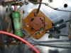
And then there was music... Well I found the culprit causing the problem with my amp, one 390 ohm 3w resistor. Of course I know there's more to it than that,I'm sure something had to cause the resistor burn up. Anyway I posted a pic of the resistor in question.

Terry
 

Attachments

  • 20160403_113955.jpg
    20160403_113955.jpg
    110.7 KB · Views: 44
Maybe -- but that resistor is dissipating nearly 2 watts under normal conditions, so it may just have given up the ghost. So is the next one down the B+ line. The next most likely cause is C20 (on my schematic) -- the HV can cap. Either way, with that resistor open, it kills the whole thing.....

Good luck with it!

Dave
 
Hey Dave... I've already replaced c20 with individual caps. I was just kinda working my way down the parts list with caps I had on hand. I was actually getting ready to change out c23,28 the 3000uf caps when I noticed the 390 ohm resistor.

Terry
 
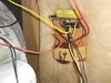
Hey Everyone, While I'm waiting for the rest of the caps to arrive I decided to work on the crossovers. So can someone decode the value of the cap from the attached pic.

Terry
 

Attachments

  • 2016-04-06 12.20.32.jpg
    2016-04-06 12.20.32.jpg
    90.9 KB · Views: 39
Looks like 1uf @ 200v dc. The problem is there are NO 1uf caps in the x-overs. You're supposed ot have 100uf, 25uf 18uf, and 3uf. So, trace the wire from both sides of the cap to either a dead end, the molex plug on the amp, or a speaker. And trace it out on the speaker / x-over drawing in the manual.

Can you take a picture of the WHOLE speaker cabinet and close up's of any/all caps in the cabinet. There may be a couple mounted on the speakers. Need to see them. That resistor next to the yellow cap, doesn't make any sense in there. The only resistor is supposed to be a 4.7ohm, and that one looks like a 39 ohm.

The 3000 uf MAIN CAPS DO NOT connect to chassis ground directly. Look at all wiring from the bottom of the cans, both on the center lugs and any that come off the perimeter lugs. Take multiple pictures and draw it out noting which wires goe where and color of wire. Tape each and number it and the notes. One of the caps is set up to provide NEGATIVE Voltage and the other POSITIVE voltage. These two if you inadvertantly ground either one, the whole amp fries. The fuse will keep it from catching fire, but the output transistors WILL be taken out. The safest way to replace these is to restuff them and replace the phenolic wafer if it's cracked or broken. They are brittle so replacing them is a good idea.

 
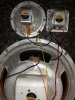
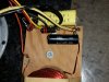
Larry here's a couple more pics of the speaker arrangement, I only see 2 caps. I measured the sprague which read .19nf on my meter.
 

Attachments

  • 20160406_212823.jpg
    20160406_212823.jpg
    55.9 KB · Views: 27
  • 20160406_212905 2.jpg
    20160406_212905 2.jpg
    67.7 KB · Views: 27
In circuit or out of circuit? Best is out of circuit as you'll pick up the rest of the components with it in circuit.
Looks like FISHER Cheesed out on the speakers and X-OVER here on this one. Supposed to be a 12" woofer, 5" mid and a 2-1/2" tweeter. X-over is supposed to be 2 coils, 3 caps and 2 resistors. Open up the other side and check to see if it's the same or different.

Wait a Minute. FISHER Never used spragues in the xovers. They used COLLINS caps almost exclusively. So that sprague is wrong.

Get the value of that Collins underneath. It should be an 18uf but it's probably a 4uf

It's a good possibility that either FISHER cheaped out or someone was inside here and screwed it all up. It's not matching up with any of the speaker schematic I've checked back to 1961. So you'll need to rebuild it from the ground up.

Count the caps and the resistors total along with the values. . And please compare the other side too. If different I need all the parts values and total count.

This is the 1964 Ambassador speaker system schematic with parts list. If there are 2 coils (inductors) you're ok. If not I don't know what size they are and no idea how to figure out what's needed. As far as the caps and resistors are concerned the caps are bipolar (non polar) electrolytic's, and the resistors can be 1/2watt carbon film or metal film.

ScreenHunter_291 Apr. 06 23.37.jpg
 
Last edited:
Larry... Before I left for work this morning I pulled the other back off and it's identical to the other. Oh, and I did check the capacitor in circuit.

Terry
 
then FISHER Cheaped out on the X-Over. It resembles a Custom Electra x-over. You can recap it as is, or build it to the manual. That is gonna be hard as there are no specs on the inductors.
 
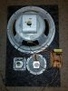
Here's a pic of the complete speaker panel pulled out of the console. Wonder how often Ambassador crossovers show up on the Bay. Did Fisher make a floor set that utilized the same 3-way speaker compliment?

Terry
 

Attachments

  • 20160407_195836.jpg
    20160407_195836.jpg
    89 KB · Views: 32
  • 20160407_195655.jpg
    20160407_195655.jpg
    62.8 KB · Views: 31
That looks like my '65 Futura speaker's but my midrange has an isolation can on it.
Very very rarely do compete x-overs show up on e-Prey. Best thing is to just rebuild it to specs for the unit.

I found it, and figured it out! It has a 64 Futura speakers and x-over with the caps changed from 6uf and 2 uf to 4 and 1 uf. The resistors are 22 and 33 ohm. Plus 1 coil.

The Ambassador and Futura used pretty much everything with the exception most of the time of the speakers. The ambassador usually got twin mids where the Futura got a single mid. The amps and tuners/preamnps are identical and they interchanged a lot of stuff. It's possible that the line ran out of Ambassador assemblies and used Futura's.

Just get the parts as set up in the '64 Futura manual. Rebuild them both and call it a day.
Parts express has the caps. Resistors are normal 1/2watt resistors.
 
Larry...Your the Man! But what about the fact that the 64 Futura shows two inductors in the schematic, Is that an issue or just rebuild as is?

Terry
 
J. H. KEE-RIST! (that's for me!). I goofed. It's a '63 FUTURA x-over and spkr setup not a 64. I was looking at the '63 manual and thinking '64. Usually the ambassador uses the same operating gear, EXCEPT FOR THE SPEAKERS as the futura. Like I said above the Ambassador has 2 mids, vs. 1 in the Futura. and 2 coils vs. 1.

Don't use the Ambassador spkr diagram as there is an extra coil and an extra spkr that you don't have.

It was a long night last night. Wife is under the knife right now having foot surgery on right foot, so I've been up for the last two days. Here's what i figured out with a little more research.

I see a 22 ohm resistor out in the open. There is a resistor that I can't make out underneath the sprague. If it's one of the following values use the diagrams from the manuals listed below.

1.) USE THE 63 FUTURA MANUAL if the RESISTOR VALUES are 22 and 33 ohms on yours. Use the cap values in the manual. 22 ohm is Red Red Blk. 33 ohm is Org Org Blk

2.) Use the '63 Custom Electra Manual if the Resistor values are 22 and 10 ohm. Use the cap values in the manual. 22 ohm is Red Red Blk, 10 ohm is Brn Blk Blk.

FISHER did some weird stuff in the mid 60's. Getting rid of extra stock assemblies and putting them in other units was one of them. So it's not really surprising.
 
Thanks.

So far so good. She'll be on crutches or cane for a few weeks but it looks good now.
 
Getting ready to order my coupling caps for the 690 and was wondering what recommendations you all had. The originals are 100uf 25v axials. Are orange drops ok for this application?

Terry
 
Back
Top Bottom