• The move to the new server is done. There are some software and database maintenance updates in process. This has us passing the hat around to help out. We appreciate any donations. Seriously, even a dollar helps. The payment page may be found here - https://www.audiokarma.org/support.html

1964 Fisher Ambassador

C11 thru C14 are part of the BIAS CIRCUIT, NOT COUPLING CAPS! Use Nichicon 100uf 35 or 50v TVX series caps for these. There are NO OUTPUT COUPLING CAPS. If the pots are still there and connected DO NOT TOUCH. There is a very specific procedure and you will need to adjust them both at the same time. Hard enough for most tech's to do correctly, almost deadly to the amp if a non tech does it.

647-TVX1H101MAD1LS is 100uf 50v
647-TVX1V101MAD is 100uf 35v

100uf 25V Orange drops would be about as big as a grapefruit. Any electrolytics in the chassis bump the voltage up 1 level minimum to handle the increased wall voltage and attendant increase in B+ voltages.
 
Last edited:
Hey Everyone, Well back from my mini vacation and back to the Ambassador. Speaker crossovers have been re-capped which leads me to this question. I noticed on the inside of the speaker cabinets there is insulation on the out walls and the back covers to the cabinets. would it improve the acoustics at all if I were to put insulation on the top bottom and the inside walls of the cabinets?

Terry
 
You can try it. It's one of those things that is more of a personal thing. I havne't noticed any difference with the FUTURA by adding 1" of insulation on the plain sides.
 
Hey Larry, A quick question. I noticed on one of your previous post of a re-cap on a 690-a that you mounted the 3300 uf caps under the chassis instead of stuffing the originals. I was wondering if you had any close-up pics of your work that I could see. I'm just not comfortable trying the re-stuffing route at this time.

Terry
 
That was either a 49A or 59A, which the 690 is closest to. I soldered 5 lug terminal strips to the side wall, and then wired it all up. Not sure if I have pics of that or not, I'll check tho.

2 or 3 sections of the 4 section lead directly up to the line of 390 ohm resistors on the back wall of the chassis. I followed theleads from the can cap directly back to the resistors, mounted the positive lead on the resistor lead on the terminal, and then attached the - lead of the cap to the ground lug underneath on the terminal strips. Cut's out a lot of wiring that could pick up hum too. Let me see about those pics.

Found some of 2 different amps I did.
Stock 49A amp. 59A is predominately identical except for transistor side.
65 fisher amp.JPG

1st iteration of caps inside This is a 59A amp (which is basically a 690A) Note the extra 4 transistors from the 49A.
49A and 59A amp porn.JPG


2nd iteration of caps internal. Note diode bridge instead of 4 diodes. Also C20A,B,C are between 390 ohm resistors.

100_4567.JPG


Close up of P.S. Corner. Tape over the ends of the 3300uf caps so they don't short to the chassis.(BAD JU-JU!) With the bridge rectifier, you have more room to move things around so they don't touch each other.

100_4568.JPG
 
Last edited:
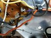
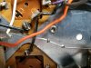
Got a couple more questions on the 3300uf caps. In picture 1 it's ok to tie the purple and the black wire to the same point on a terminal strip. Am I correct? And in picture 2 can I tie the + and - cap leads together? In case your wondering, yes I'm freaking out with these two doubler caps.lol! I know I'm probably making it a lot harder than it needs to be, just don't need the fireworks to take out 8 good transistors.
 

Attachments

  • 20160504_212409.jpg
    20160504_212409.jpg
    97 KB · Views: 23
  • 20160504_212445.jpg
    20160504_212445.jpg
    96.8 KB · Views: 18
Lets look at the leads in picture 1. From top to bottom, you have for this example On Cap #1 pin A, Pin B, Pin C Pin A & C are both NEGATIVE LEADS ON THE CAP, so YES they can go to the same terminal. Pin 2 is a POSITIVE that goes to the negative (pin4) on CAP 2.

In PICTURE 2. The Positive on the upper cap (pin2) carries over to the negative on (pin 4) on Cap 2. This is the voltage Doubler part of the Power supply. As an analogy take 2 "D" cells and place them in series so you get 2 inline. These are in series so when you hook up a meter you get 3 volts instead of 1.5volts. The leads are looking from the front to back .....POSITIVE.........NEGATIVE(1st battery), then POSITIVE......NEGATIVE. The caps are hooked up in series to double the voltage. So YES, The Pin2 to Pin 4 lead is correct.
 
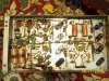
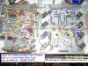
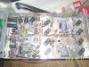
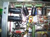
Update on the Ambassador, I've re-capped the tuner but now I have a hum at warm up, but once it's warmed up and playing it is dead quiet. I replaced the 2-60uf caps, the 40uf and 20uf in the can. I did move some of the original wiring in doing so. Any ideas on what to look for, or can I just let it go since it's only last a few seconds.

Terry
 
It could also be induced hum from the moved wiring too close to audio wiring. Move them back to where they were.

Had the same problem on my '51 Coronet with 6v6's. Grossly mismatched 6v6's. New set and the hum stopped. Added some circuit changes developed by Dave to keep it from coming back.

Make sure all the tube pins are making good contact. Wiggle each tube slightly to see if that affects the hum. If the wiggling stops the hum at any tube, re-tension and clean the socket pins and that tubes pins. Don't worry about the RF tubes (6au6, 6ba6, 6be6, 6aq8, 6hs6,6gk5 types). You'll be doing all of the preamp tubes on the tuner/preamp chassis, and the 3 tubes on the amp chassis. Mainly 12ax7's and the 6HU8's. Highly unlikely the RF tubes are causing this problem.

If it's only for a few seconds during warmup and before sound develops, you can probably not worry about it as much as a steady state hum. But any hum is aggravating. start with wiggling all the tubes during warm up. You will have to cycle the power on and off a number of times before all tubes are done. Give the tubes at least 5-10 minutes between power down and power up. It will take a good while, but you won't lose any tubes due to short cycling. Short cycling can shock them into a short circuit, and other problems.
 
Thanks Larry. I'll check the 12ax7's on the tuner. It was playing fine though before I worked on the tuner. I also have some rather ugly solder joints,(I'm not very good at it) that I'll check also. I did try moving some of the wires around while it was humming but that had no affect on it.
On an unrelated question as to the tuner, Has anyone out there posted the teardown procedures for the Garrard Type A changer? It's going to need a little attention also.

Terry
 
Not that I'm aware of. Get a couple of can's of CRC Non Residue electronics cleaner, and spray all the old grease off the undersides. Relube the spindle bearings, and whereever parts slide together. Oil with minimal amounts of sewing machine oil, all bearings. Pull off the platter and degrease the inside of the platter. remove the idler wheel, Wash in HOT WATER and DAWN Liquid SOAP. RINSE, and DO NOT TOUCH the rubber parts with bare hands (skin contaminants). drop of sewing machine oil on the idler wheel shaft. Clean the motor spindle. Do NOT TOUCH with bare hands, the motor spindle, the idler wheel rubber or the inside of the platter. Any body oils will cause slippage.

If the idler wheel inspection shows cracks along the edge, Hardened rubber on the edge, glazing on the edge, or rubber cracks on the sides, replace the idler. www.thevoiceofmusic.com has replacement idlers for $28.00 with the old one as a core. OR you can send it off to TERRY's Rubber Rollers.

99% of the time, just cleaning the old concretious lube off and relubing, plus idler wheel cleaning / replacement is all that's needed.
 
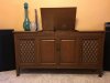
The 1964 Ambassador Is complete!!! Thanks to everyone out there who answered many questions of mine, Especially you Larry. The unit sounds amazing. So thanks agains. I've posted a few pics of my pride and joy.

TerryIMG_0835.JPGIMG_0837.JPG
 

Attachments

  • IMG_0838.JPG
    IMG_0838.JPG
    76.4 KB · Views: 10
OUTSTANDING! If it sounds 1/2 as good as it looks, fantastic. You've got a beauty there. Do the usual maintenance cleaning of switchesand pots every two-three years, and you'll have it long enough for the grandkids to scratch their heads trying to figure it all out.
 
Last edited:
Terry, I have read your entire story and process as I am contemplating picking one of these up tomorrow. Yours has the better looking cabinet but I think they are the same and mine is not working. I posted up asking about anything in particular to check for but since it isn't working, not much to verify other than cosmetics. Great job!

Bill
 
Last edited:
Bill, Did you get the Fisher? When I went to pick mine up ( about 3 hrs away) it was dead in the water. It was advertised as working on CL and it did power up but couldn't get any kind of sound out of her. The lady had it advertised at $125.00 but I got it for $50.00 since it wasn't working. When I got it home and got the amp out of it is when I found the 390ohm 3watt resistor that was bad. Let me know if you need any help, but I'll be honest I'm not nearly as my knowledge is a lot less than the others on the Fisher site. By the way I've got a complete second amp that I bought in case I couldn't get the original to work. It does need a complete re-cap because it has a pretty good hum when it's powered up.

Terry
 
Back
Top Bottom