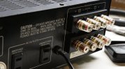
Sorry for the thread necromancy, but an old (and ignored) alert brought be back to this fab thread… and since I happen to have my personal ‘717 on my li’l bench for some basic maintenance and cleaning, I thought it a perfect opportunity to show just how easy adding binding posts to the ‘717 can be!
What you need:
• Choice of binding posts: I prefer Pomona 4243-0 and 4243-2 binding posts for their solid quality, wide availability, and they just look nice, y’know? -0 and -2 denote base color, black or red, respectively. Mueller Electric makes a near-perfect copy of the Pomonas for the same price, part no. P4243-x. With such similar p/n’s, they gotta be licensed… right? Anyway…
•• On this particular ‘717 I used Keystone 7018’s and 7019’s - they’re what I had on hand at the time and they’ve proven perfectly adequate. A little “chunkier” than the Pomonas, but who cares if they’re facing the wall most of the time?
• An appropriately sized piece of acrylic sheet (aka plexiglas, lexan, acrylite, lucite, palsun, polygal, makrolon, &c…) to mount the binding posts on. It’s been a while since I first assembled it so I can’t be sure the exact thickness, but knowing what I keep on hand, I’d say 3/16” - 1/8” thick.
The piece itself is roughly 3 3/8” x 3 3/8” and is secured with four M2 screws with flat washers on the outside and teeny-tiny lockwashers behind nuts on the inside.
Pretty sure I must have drilled the holes for the fasteners. It’s easy - just lay down some painters tape over the area to be drilled, use a combo square to draw your lines and mark your points, double check, and drill away!
I believe the attached photos should be enough to go on to guide you through final assembly.
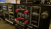

I had originally planned to paint the inside of the plexi, but, well, I didn’t. Can’t hardly tell it’s clear unless you shine a flashlight through it - and it sure looks cool when you do!
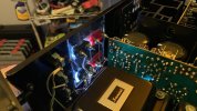
Wiring the outputs to the posts couldn’t be easier, there’s enough slack from the factory that it really wasn’t a problem.
Negative/ground/(-) terminals are wired together PER CHANNEL, NOT ALL TOGETHER. Sorry, felt that was worth yelling just in case someone either doesn’t know how this stuff works and/or didn’t pay attention to the pics. Just a nice fat solid wire between the (-) terminals, straight down, Right A to Right B, Left A to Left B. I don’t think I can make this one point any clearer so I’ll drop it here.
Happy hunting