OK on no additional photos. Should the device be powered on to checked for the DC voltage?Those photos are OK, no need for another.
So you measured DCV from the + terminal to - terminal on each of the 10,000uF caps and you read 0VDC, yes?


You are using an out of date browser. It may not display this or other websites correctly.
You should upgrade or use an alternative browser.
You should upgrade or use an alternative browser.
2250B is not powering on at all
- Thread starter Jomo1960
- Start date

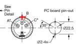
Here is what I think your capacitor terminals look like.
There is one lead that is located by itself, the - lead.
The other lead is the middle lead of the group of 3, the + lead.
The bar should connect the - lead of one cap to the + lead of the other cap.
But to measure voltage with your DMM, connect the - (black) DMM probe to the bar then attach the + (red) DMM probe to the + cap terminal.
To measure the other cap, leave the black lead on the bar, but move the red lead to the - terminal of the other cap.
There is one lead that is located by itself, the - lead.
The other lead is the middle lead of the group of 3, the + lead.
The bar should connect the - lead of one cap to the + lead of the other cap.
But to measure voltage with your DMM, connect the - (black) DMM probe to the bar then attach the + (red) DMM probe to the + cap terminal.
To measure the other cap, leave the black lead on the bar, but move the red lead to the - terminal of the other cap.
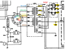
We need to check the AC input and output from the transformer, but I need to know how the jumpers are located when you plug it in for 120VAC.
It will look something like this, but for 120V.
The plug in the 120V position will jumper one pin to another. I need to know which pins (by number) are jumpered.
Maybe another member will know this, but I don't have one like yours in front of me... all I have is the SM.
It will look something like this, but for 120V.
The plug in the 120V position will jumper one pin to another. I need to know which pins (by number) are jumpered.
Maybe another member will know this, but I don't have one like yours in front of me... all I have is the SM.

Check for continuity, Voltage or both? DC Volts?Did I miss in reading.
Have you checked power to the switch?
Answer 1: About the plug... NO I want to see the part on the other side that plugs into that socket.
Photo of the front and back side of this... (circled in red)
I want to know what pins in the plug are connected to what holes in the socket.
With power off/unplugged, unscrew the plastic screw in the center and pull the disc out (make note of where it was positioned so you can put it back).
Take a picture of the front of the plug, back of the plug, and front of the socket on the rear panel.

Answer 2: Check power with power switch in ON position.
You can check it with your DMM, ACV at the two points circled... OR...

Just plug a lamp into the switched power outlet on the back of the receiver and see if it lights up when you press the Power switch ON.

Photo of the front and back side of this... (circled in red)
I want to know what pins in the plug are connected to what holes in the socket.
With power off/unplugged, unscrew the plastic screw in the center and pull the disc out (make note of where it was positioned so you can put it back).
Take a picture of the front of the plug, back of the plug, and front of the socket on the rear panel.
Answer 2: Check power with power switch in ON position.
You can check it with your DMM, ACV at the two points circled... OR...
Just plug a lamp into the switched power outlet on the back of the receiver and see if it lights up when you press the Power switch ON.
Yes, coincidentally I just verified the power switch in a similar wayAnswer 1: About the plug... NO I want to see the part on the other side that plugs into that socket.
Photo of the front and back side of this... (circled in red)
I want to know what pins in the plug are connected to what holes in the socket.
With power off/unplugged, unscrew the plastic screw in the center and pull the disc out (make note of where it was positioned so you can put it back).
Take a picture of the front of the plug, back of the plug, and front of the socket on the rear panel.
View attachment 3844092
Answer 2: Check power with power switch in ON position.
You can check it with your DMM, ACV at the two points circled... OR...
View attachment 3844100
Just plug a lamp into the switched power outlet on the back of the receiver and see if it lights up when you press the Power switch ON.
View attachment 3844095
Sorry, I can't help you figure out if you are getting power to the transformer if you don't answer my previous questions.
Let me try to explain:
Let me try to explain:
- The 120VAC that comes into the receiver goes to the transformer primary windings.
- But since you have an international version, the input AC voltage to the transformer is determined by the jumpers in the voltage selector plug that I am referring to.
- So what I had asked for is to remove the voltage selector plug, take some photos of the front and back side, then put it back.
- Also, while you have the voltage selector out, take a photo of the voltage selector socket that is mounted to the chassis.
What could be easier than plugging in a table lamp into the switched socket, turning on the lamp switch, then pressing the 2250B power switch IN and seeing if the lamp turns on?OK, it was not easy but I verified that the switch has continuity and does have 120 v going through but using the terminals by the plug and the accessory outlet.
Hi,
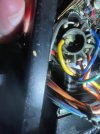
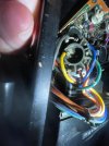
I really am sorry if you think that I am trying to follow your instructions. I was doing something else along with getting help from you. You have my complete attention now. I attached what I hope is the picture that you asked for and I verified that the switched outlet on the back of the Marantz is only live when the power switch is on.
I really am sorry if you think that I am trying to follow your instructions. I was doing something else along with getting help from you. You have my complete attention now. I attached what I hope is the picture that you asked for and I verified that the switched outlet on the back of the Marantz is only live when the power switch is on.
Attachments
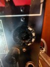
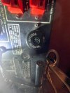
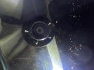
Yes, but the photo is so dark that I can't even see where the voltage notch is on the 2nd photo. Can you add some light to it and take another photo so I can see the relative position of the notch to the pins or the pin numbers on the back? Do you work by candle light?
Let's make this easy for you to do. 
Can you set your DMM to measure ACV.
 BE CAREFUL - HIGH VOLTAGE on the transformer. Do not touch any metal on the DMM probes while you are moving them.
Do not touch the chassis with your other hand while probing the transformer wires.
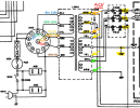
Can you set your DMM to measure ACV.
- Put the black lead on one color wire and the red lead on the other same color wire.
- Measure the AC voltage between the ORANGE wires.
- Measure the AC voltage between the YELLOW wires.
- Measure the AC voltage between the GREEN wires.
- Please tell me what you measured.
BE CAREFUL - HIGH VOLTAGE on the transformer. Do not touch any metal on the DMM probes while you are moving them.Do not touch the chassis with your other hand while probing the transformer wires.