You are using an out of date browser. It may not display this or other websites correctly.
You should upgrade or use an alternative browser.
You should upgrade or use an alternative browser.
2250B is not powering on at all
- Thread starter Jomo1960
- Start date


With power-on, you measured AC volts between sets of colored wires and got 0V for all?
Just to make sure, these are the wires coming out of the same side of the transformer, not the primary side?
I think there should be 6 wires ORG(2), WHT(1), YEL(2), BLK(1), GRN(2).
Just to make sure, these are the wires coming out of the same side of the transformer, not the primary side?
I think there should be 6 wires ORG(2), WHT(1), YEL(2), BLK(1), GRN(2).
- Measure the AC voltage between the ORANGE wires. = 0V
- Measure the AC voltage between the YELLOW wires. = 0V
- Measure the AC voltage between the GREEN wires. = 0V
Thanks for questioning what I did. I am confused, unless I am missing something, because how can I get probe onto the wire that is inside the transformer. I made the test by the wires from the the three fuses.
Ok, I think I understand now. There are two orange wires coming out of the transformer and you want me to probe the other ends and tell you the voltage. OK. Im on it.
Ok, I think I understand now. There are two orange wires coming out of the transformer and you want me to probe the other ends and tell you the voltage. OK. Im on it.

OK, I see that you gave me the thumbs up. The ACV across those two orange terminals is 0vPlease confirm what I am looking at is correct. I followed the two heavy orange wires from the transformer to the other ends which I circled in my attached diagram. Is this one of the one location you want me to measure?
The two yellow wires should go to one side of fuse FR03 and the other to fuse FR01.
The two green wires should go to one side of fuse FR01 and the other side to chassis ground.
The two orange wires go to the bridge rectifier as you show in your photo.
See if you get any voltage on the YEL and GRN wires. If not we need to check the input to the transformer.
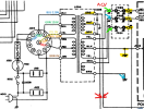
The two green wires should go to one side of fuse FR01 and the other side to chassis ground.
The two orange wires go to the bridge rectifier as you show in your photo.
See if you get any voltage on the YEL and GRN wires. If not we need to check the input to the transformer.
I'm sorry, but I don't recall you providing those voltages to me three times. I looked back at your previous posts and did not see any voltages to the fuse inputs provided by you. I see where you checked continuity. Please tell me the Post #'s and I will review your comments and data.
Last edited:
It doesn't matter that you asked me a few times. I am just reminding you so we can move ahead. The voltages across the fuses were mention in posts 6-7 and 41-42 and then again in post 50.
All that matters is that in the end I/we figure out what the problem is. I truly appreciate your help. I am trying my very best to follow your instruction to make things easier for you.
All that matters is that in the end I/we figure out what the problem is. I truly appreciate your help. I am trying my very best to follow your instruction to make things easier for you.
Just to clarify what I am asking, I don't want the voltages ACROSS THE FUSES, I am asking about the voltage between wires going to the fuses from the transformer. See diagram below.The voltages across the fuses were mention in posts 6-7 and 41-42 and then again in post 50.
Post #50 is my post not yours.
Post #6 is my post where you did not do as I asked. Post #7 is where you measured from each fuse to GND... not from transformer lead to lead. Also, you did not say you measured ACV or DCV.
Post #41 is my post. #42 is saying that you got 0v same as before, but if you are referring to post #6 it is not what I asked.
OK, because you say that you can't trace the yellow and green wires, you can measure them at the fuse board.
Please measure the ACV from YEL arrow to YEL arrow.
Please measure the ACV from GRN arrow to chassis GND.
I don't think you did this before, but if you did please
If you get 0V for all three sets of wires, then you either have a problem on the primary side of the transformer or a bad transformer, but it takes so long to get answers from you that it will take another 5 days to get what we need to determine if it is really bad.
Thank you.
Last check...
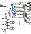
Last check...
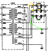
- On the transformer input side measure the ACV from the BLU wire to the GRN wire, then from the BLU wire to the YEL wire.
- Next, again on the input side measure the ACV from the ORG wire to the BRN wire, then from the ORG wire to the RED wire.
- These wires will go to the back side of the voltage selection socket.
It looks like the voltage is not getting through the voltage selector to the transformer, but it's hard to tell because I can't figure out the wiring.
Can you look for pin numbers on the voltage selector socket. I don't know if it is on the front side or back side.
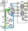
Can you look for pin numbers on the voltage selector socket. I don't know if it is on the front side or back side.
- From the schematic, one side of the AC input goes to Pin 1 (and Pin 2), blue highlight and the other side, green highlight goes to Pin 7 (and Pin 8) on the voltage selector.
- With power OFF and UNPLUGGED, set your DMM to measure Ohms and connect it to one side of the plug.
- Connect the other DMM probe to each pin on the socket until you find a connection (0 Ohms).
- There should be two of them. That would be either 1/2 or 7/8.
- Do the same for the other contact on the AC plug.
- Make note of which side of the plug connects to which pin(s).
- Next, (Be Careful) plug the AC cord back into the outlet and push in the power switch. Measure the ACV between Pin 1(2) and Pin 7(8).
- You should read line voltage of 120VAC.
Here is a summary of the voltages that you measured.
From what I can see, the 120VAC is not getting to the voltage selector socket. because all of the transformer primaries you measured are 0V.
Can you measure from pin 1 or 2 on the socket (BRN wire) to pin 7 or 8 on the socket. You should have 120VAC.
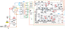
The photo of the voltage selector plug you posted has 4 pins.
Can you tell me which pins on this voltage selector plug are connected to which pins?

From what I can see, the 120VAC is not getting to the voltage selector socket. because all of the transformer primaries you measured are 0V.
Can you measure from pin 1 or 2 on the socket (BRN wire) to pin 7 or 8 on the socket. You should have 120VAC.
The photo of the voltage selector plug you posted has 4 pins.
Can you tell me which pins on this voltage selector plug are connected to which pins?