

You are using an out of date browser. It may not display this or other websites correctly.
You should upgrade or use an alternative browser.
You should upgrade or use an alternative browser.
2250B is not powering on at all
- Thread starter Jomo1960
- Start date

Here is a table that you can use to check continuity between pins (not on the socket, but on the plug).
Power off, pull the voltage selector plug off and check continuity between the pins.
C is not a pin but the contact in the center of the plug.
Example: the first square is "C to BRN"
Fill in only the white squares, the gray ones are the reverse of the others.
NOTE: C is the center conductor ring (see yellow arrow in your photo below)


Power off, pull the voltage selector plug off and check continuity between the pins.
C is not a pin but the contact in the center of the plug.
Example: the first square is "C to BRN"
Fill in only the white squares, the gray ones are the reverse of the others.
NOTE: C is the center conductor ring (see yellow arrow in your photo below)
Last edited:
See my updated photo above. C is the center ring.Not sure what C is? I'm starting the rest.
Thanks. Based on your tests and prior voltage measurements, I think this is the AC path to the transformer. I included all of the prior voltage measurements that you made.
But, there are two that we didn't make and hopefully you will get good results when you measure these.
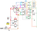
But, there are two that we didn't make and hopefully you will get good results when you measure these.
- I have shown two AC paths, one from the fuse F001 to the voltage selector jack J023 Pin 7.
- Follow the pink dashed lines:
- Voltage comes in on Pin 7
- Voltage Selector jumpers it to Pin 5
- The green wire goes to transformer primary center tap
- Comes out of transformer on the YEL wire then to Voltage Selector "C" contact
- "C" contact is connected to Pin 1 and the BRN wire
- Pin 1 connects to the 120VAC input
- The 2nd path goes from Pin 7 to Pin 3 (or Pin 5 to Pin 3) to the transformer primary center tap RED wire
- It goes through the transformer and comes out on the BRN wire which also is connected to Pin 1
- The BRN wire is the 120VAC return.
- Transformer GRN to YEL wire ACV
- Transformer RED to BRN wire ACV
Is Pin 7 to Pin 1, the same as red to brown on the voltage selector? If yes, then the voltage from Pin 7 to pin 1 is 0 vac.So it looks like AC power is not even getting to the Voltage Selector plug.
Measure ACV from Pin 7 to Pin 1. If it is not 120VAC, then you need to pull and measure the resistance of fuse F001. It should read 0 Ohms.
OK, you previously measured 120 VAC on the switched outlet on the back of the receiver.
The only difference is that the fuse F001 in in between those two points.
Check the voltage from the brown wire to one wire coming from the fuse holder, then check the voltage from the brown wire to the other wire on the fuse holder.
What do you get?
The only difference is that the fuse F001 in in between those two points.
Check the voltage from the brown wire to one wire coming from the fuse holder, then check the voltage from the brown wire to the other wire on the fuse holder.
What do you get?