

You are using an out of date browser. It may not display this or other websites correctly.
You should upgrade or use an alternative browser.
You should upgrade or use an alternative browser.
2325 mystery problem
- Thread starter klamsoss
- Start date
-
- Tags
- marantz 2325


catrafter
Marantz Specialist
I am at a loss as to why F801 is more susceptible to 'blowing' after recapping, but I am convinced that it is.
C806 is ahead of the fuse, so that can't be a factor, C807's charging is current limited by R805, so that pretty much leaves the circuitry that is powered by the +35V buss (J805) to wit, JH09,
J406, J408, J314, JU05, JE01, JE10 and JT23.
If someone has any information on this I would be very interested in hearing about it.
Tom
C806 is ahead of the fuse, so that can't be a factor, C807's charging is current limited by R805, so that pretty much leaves the circuitry that is powered by the +35V buss (J805) to wit, JH09,
J406, J408, J314, JU05, JE01, JE10 and JT23.
If someone has any information on this I would be very interested in hearing about it.
Tom

klamsoss
Be willing to fail and try again.
Sorry for the delay, all. I've been screwing around with a rotel cd player that is intermittent... in that if you smack it around a little it'll work, but the display won't... anyway, that's a story for a different thread.
I fired up the desoldering station for an hour tonight and started checking things. The outputs are all testing okay. Not the most perfectly matched I have ever seen but not terrible either. There are no shorts in the outputs, nor in any of the diodes or transistors in the vicinity of the inductor on the power amp module.
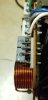
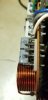
There are absolutely no indications of burned caps or resistors in the vicinity of the inductor, either. The resistors test within 5% of spec. This is just where I thought the spark and smoke came from. That's not necessarily a sure thing. Sparks have a funny way of being hard to pinpoint since they happen so fast, and when they come with a BANG, that's a bit distracting, too. At close inspection, the only area that looks heat-tarnished, and it does look heat tarnished, are the 4 pins that connect with the chassis power harness plug. I've attached a couple pictures. That plug also sits exactly below the inductor...
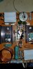
The only place on the amp driver board that looks remotely overheated is under R719 and H718. I checked R719 and it's well within spec, and H718 has been replaced. I attached a picture of that area as well, and the whole board in general. It's actually pretty clean, which makes this all the more of a head scratcher...
I haven't had a chance to get the slowblow fuse yet. What's the consensus? Stick with the 0.2A or bump it up? I suppose I could get a few of each...
Whatever is up with the amp module, the first thing is to get the rest working with the amp modules disconnected. I hook them back up, eh?
@sanjib do you happen to know what the H803 replacement transistor would be? Looks like KSC1815 ( https://www.digikey.com/en/products/detail/KSC1815YTA/KSC1815YTACT-ND/3908203?itemSeq=341710061) is the recommended one when used in power supplies?
Thanks for the help, all!
I fired up the desoldering station for an hour tonight and started checking things. The outputs are all testing okay. Not the most perfectly matched I have ever seen but not terrible either. There are no shorts in the outputs, nor in any of the diodes or transistors in the vicinity of the inductor on the power amp module.
There are absolutely no indications of burned caps or resistors in the vicinity of the inductor, either. The resistors test within 5% of spec. This is just where I thought the spark and smoke came from. That's not necessarily a sure thing. Sparks have a funny way of being hard to pinpoint since they happen so fast, and when they come with a BANG, that's a bit distracting, too. At close inspection, the only area that looks heat-tarnished, and it does look heat tarnished, are the 4 pins that connect with the chassis power harness plug. I've attached a couple pictures. That plug also sits exactly below the inductor...
The only place on the amp driver board that looks remotely overheated is under R719 and H718. I checked R719 and it's well within spec, and H718 has been replaced. I attached a picture of that area as well, and the whole board in general. It's actually pretty clean, which makes this all the more of a head scratcher...
I haven't had a chance to get the slowblow fuse yet. What's the consensus? Stick with the 0.2A or bump it up? I suppose I could get a few of each...
Whatever is up with the amp module, the first thing is to get the rest working with the amp modules disconnected. I hook them back up, eh?
@sanjib do you happen to know what the H803 replacement transistor would be? Looks like KSC1815 ( https://www.digikey.com/en/products/detail/KSC1815YTA/KSC1815YTACT-ND/3908203?itemSeq=341710061) is the recommended one when used in power supplies?
Thanks for the help, all!
Attachments
Last edited:

H803 replacement is KSC2383YTA it may be a litle overkill but I have used it without any problem.Sorry for the delay, all. I've been screwing around with a rotel cd player that is intermittent... in that if you smack it around a little it'll work, but the display won't... anyway, that's a story for a different thread.
I fired up the desoldering station for an hour tonight and started checking things. The outputs are all testing okay. Not the most perfectly matched I have ever seen but not terrible either. Thee are no shorts in the outputs, or in any of the diodes or transistors in the vicinity of the inductor on the power amp module.
There are absolutely no indications of burned caps or resistors in the vicinity of the inductor, either. The resistors test within 5% of spec. This is just where I thought the spark and smoke came from. That's not necessarily a sure thing. Sparks have a funny way of being hard to pinpoint since they happen so fast, and when they come with a BANG, that's a bit distracting, too. At close inspection, the only area that looks heat-tarnished, and it does look heat tarnished, are the 4 pins that connect with the chassis power harness plug. I've attached a couple pictures. That plug also sites exactly below the inductor...
The only place on the amp driver board that looks remotely overheated is under R719 and H718. I checked R719 and it's well within spec, and H718 has been replaced. I attached a picture of that area as well, and the whole board in general. It's actually pretty clean, which makes this all the more of a head scratcher...
I haven't had a chance to get the slowblow fuse yet. What's the consensus? Stick with the 0.2A or bump it up? I suppose I could get a few of each...
Whatever is up with the amp module, the first thing is to get the rest working with the amp modules disconnected. I hook them back up, eh?
@sanjib do you happen to know what the H803 replacement transistor would be? Looks like KSC1815 ( https://www.digikey.com/en/products/detail/KSC1815YTA/KSC1815YTACT-ND/3908203?itemSeq=341710061) is the recommended one when used in power supplies?
Thanks for the help, all!
klamsoss
Be willing to fail and try again.
Okay, I'm going to pop in the new transistor for H803, and new fuse of the slow-blow variety, and then see how things work. I'm fairly confident this will resolve the power supply fuse blowing issue, and if not, I'll simply start disconnecting the various components it feeds until I find the responsible party. I'm pretty much positive it has to be the phono section or the other unidentified board next to the phono section. Everything worked flawlessly before I did those two pieces.
Assuming I resolve the fuse blowing issue, that still leaves me with the original question mark regarding what is going on with the power module. Also, not sure why it would only be the left side (unless it would be both sides but the left goes faster so the right hasn't had it's chance to put on a light show). I've tested the transistors on the offending power module, as indicated in post #23 above. I'm a fan of a good show as much as the next guy, but I'd really like to not experience the excitement of sparks and smoke again. Any input on what to look at is much appreciated.
For reference, the modifications to the power supply are detailed in the PDF attached to post #6. That post also contains a list of the modifications made to the power amp module itself. As I said before, the modifications are all based exclusively on the directions/build notes that were given to me by @hirscwi so I have no reason to think they are out of line.
Assuming I resolve the fuse blowing issue, that still leaves me with the original question mark regarding what is going on with the power module. Also, not sure why it would only be the left side (unless it would be both sides but the left goes faster so the right hasn't had it's chance to put on a light show). I've tested the transistors on the offending power module, as indicated in post #23 above. I'm a fan of a good show as much as the next guy, but I'd really like to not experience the excitement of sparks and smoke again. Any input on what to look at is much appreciated.
For reference, the modifications to the power supply are detailed in the PDF attached to post #6. That post also contains a list of the modifications made to the power amp module itself. As I said before, the modifications are all based exclusively on the directions/build notes that were given to me by @hirscwi so I have no reason to think they are out of line.
klamsoss
Be willing to fail and try again.
2325 schematic says 0.2A for the power supply board fuse. The comments discuss that after recapping for some unknown reason this model seems to blow that fuse and a modest increase and switch to a slow-blow type is the recommended fix for the problem.I haven't read all the comments but I can't believe that fuse at .2 amp can be correct. I have an 250M schematic in front of me and that fuse is 4 amps.

Leestereo
Super Member
It is odd that F801 blows on power up. IIRC, the fuse is only for the regulated 35VDC and the 19VDC supplies, so the power amplifier stage does not draw on this supply. Unless there was an error during the recap of the P800 board, the current draw is downstream from the power supply itself. Have you tried powering up with the preamplifier board disconnected?
catrafter
Marantz Specialist
It is odd that F801 blows on power up. IIRC, the fuse is only for the regulated 35VDC and the 19VDC supplies, so the power amplifier stage does not draw on this supply. Unless there was an error during the recap of the P800 board, the current draw is downstream from the power supply itself. Have you tried powering up with the preamplifier board disconnected?
I haven't. The fuse 'failing' has been sporadic, when it occurs at all.
Tom
klamsoss
Be willing to fail and try again.
I was able to identify that C413 on the phono board was silkscreened in the wrong orientation when it blew and took R434 with it. I also replaced H409 with 2 (in series) 1n4148.
I did this without either power amp modules hooked up. These cap and resistor blew after about 45 seconds from startup. The 0.25A slow blow fuse I substituted for the 0.2A fast blow type did NOT blow.
I've now fired it up (still without the power amp modules in place) and adjusted the power supply voltage to 35V as indicated in the service manual. I let it sit and run for 5+ minutes so I'm now convinced there aren't other issues with current draw when the power modules are no longer hooked up. SO, problem 1, solved.
Now it's time to hook up the main power amp modules, but I still haven't identified anything amiss with them and it's never good practice to keep running ANY electronic equipment that isn't working properly (not least an extremely nice, and costly audio amplifier that doesn't belong to me). As I said above, I'm reluctant to fire it up with either one hooked up since (A) I don't know what the issue was with the left one, and (B) I don't know if it might ALSO be a problem on the right one, since they both got exactly the same treatment.
Any ideas, going back to the original problem of the power amp modules? I assume the phono section cap polarity issue is unlikely to be the source of a problem in the power module, especially since I didn't have the selector on phono when the problem happened.
If I do need to fire it up again to try and identify the issue, would it be better to use 100w dummy loads or test speakers?
It was suggested to hook up the oscilloscope and look for oscillation but I haven't done that before. Do so I don't really know the procedure. Would I just hook up my 'scope to the speaker outputs (with? without speakers? dummy loads? in place) and then what am I looking for on the scope? I assume I don't need to feed any signal, and should probably make sure it's on AUX and NOT getting any signal.
As always, many thanks for the help!
I did this without either power amp modules hooked up. These cap and resistor blew after about 45 seconds from startup. The 0.25A slow blow fuse I substituted for the 0.2A fast blow type did NOT blow.
I've now fired it up (still without the power amp modules in place) and adjusted the power supply voltage to 35V as indicated in the service manual. I let it sit and run for 5+ minutes so I'm now convinced there aren't other issues with current draw when the power modules are no longer hooked up. SO, problem 1, solved.
Now it's time to hook up the main power amp modules, but I still haven't identified anything amiss with them and it's never good practice to keep running ANY electronic equipment that isn't working properly (not least an extremely nice, and costly audio amplifier that doesn't belong to me). As I said above, I'm reluctant to fire it up with either one hooked up since (A) I don't know what the issue was with the left one, and (B) I don't know if it might ALSO be a problem on the right one, since they both got exactly the same treatment.
Any ideas, going back to the original problem of the power amp modules? I assume the phono section cap polarity issue is unlikely to be the source of a problem in the power module, especially since I didn't have the selector on phono when the problem happened.
If I do need to fire it up again to try and identify the issue, would it be better to use 100w dummy loads or test speakers?
It was suggested to hook up the oscilloscope and look for oscillation but I haven't done that before. Do so I don't really know the procedure. Would I just hook up my 'scope to the speaker outputs (with? without speakers? dummy loads? in place) and then what am I looking for on the scope? I assume I don't need to feed any signal, and should probably make sure it's on AUX and NOT getting any signal.
As always, many thanks for the help!

Steven Tate
CEO Flat Forehead Soc.
To look at amp performance with a scope, you hook the scope to speaker terminals with either a dummy load or speakers. Best to use a dummy load to save your speakers and to be able to test at high volumes up to clipping. Then use a sine wave generator into your Aux input. If you don’t have a stand alone signal generator, there are phone apps available that will work. Just make sure volume is low enough on the phone not to overdrive your preamp. The height of your output sine wave will grow as you increase volume until it clips at some high volume - noticeable by flattening of the sine wave at top and/or bottom. You will be looking for signs of something other than a clean sine wave between zero volume and clipping, and also, a flat line with very little static at zero volume.

LOL, a dummy load is called that because if you use real speakers, the sound output level of a 1K sine wave will make you a dummy by blowing your eardrums right into your brain matter, scrambling it all up. Although 50 or 100 watt "resistors" are not cheap. I ended up with 4x50 4ohm, wired them up so I can get both 4 and 8 ohm, and put heats sinks and little computer CPU fans on them, cause they can get hot if you run them long enough. But I don't, generally just a few minutes is all that's needed.
I have a bazzilion pics of amp sine wave right before clipping, but no pics showing clipping.
This works:
https://en.wikipedia.org/wiki/Clipp...signal simply "cuts,square-wave-type waveform
I have a bazzilion pics of amp sine wave right before clipping, but no pics showing clipping.
This works:
https://en.wikipedia.org/wiki/Clipp...signal simply "cuts,square-wave-type waveform
klamsoss
Be willing to fail and try again.
Sounds like I know what I'm doing then. I know what clipping looks like from prior projects, and I know how to set up my 'scope for looking for clipping, and making adjustments to balance and bias as well as DC offset and such. I just didn't know if there was something special about looking for oscillation. My 8 ohm 100w dummy loads are not quite sufficient for the rated output of this amp, but given how quickly things went bang before, I don't think I will push their limits in such a way as to cause any damage to anything. My signal generator only has one output (it's an old eico tube unit that I refurbished as best I could without a distortion analyzer), but I can either split that or test one channel at a time. I never output more than 1VAC with it when I'm feeding a signal into my equipment, and honestly it's usually more like 0.2VAC
Honestly, though, having checked pretty much all of the components already, I'm not sure what I would even do if I FOUND oscillation.
Honestly, though, having checked pretty much all of the components already, I'm not sure what I would even do if I FOUND oscillation.
Edit: Actually I should correct this in case someone see it, I looked closer at it and it is actually a 6 amp fuse for a 250M, my printout is a little blurry!I haven't read all the comments but I can't believe that fuse at .2 amp can be correct. I have an 250M schematic in front of me and that fuse is 4 amps.
klamsoss
Be willing to fail and try again.
Fired this thing up today with just the right side amp hooked up(the left side amp module was the issue before). I had output on but dummy loads hooked up so I couldn't listen for output, but I had no issues with it that I could tell. I still can't figure out why the issue with the phono board cap being reversed would cause a problem in the left amp module, but it seems clear that there's no major issues with the right side amp module being hooked up. I let it run for about 2 minutes to make sure things were still working properly after a bit of heat got into the components.
I am going to try it out with the left side amp module hooked up, but I don't like it. I really don't like to try something out before I have identified the issue but I have checked everything I could think of, and pretty much everything suggested here, so I'm not sure what else to do. I'll have it hooked up to my 'scope, so hopefully if it is an oscillation problem, that will show up right away. Initially, I'll have the speaker output off, and if things seem okay, I'll turn the output on, dummy loads hooked up, and I'll be feeding it 0.8VAC 1000Hz signal through the aux input. Also going to video record things to make sure I know exactly what happens and when, if anything happens.
For the record, I have a 0.25A slow blow fuse on the power supply board now. I may try and go back to the 0.2A fast blow type after I get everything else sorted out but since there seems to be a consensus that there's no problem running it with the 0.25A fuse, and I don't want to just keep replacing them over and over, I'll continue with that for the time being.
I am going to try it out with the left side amp module hooked up, but I don't like it. I really don't like to try something out before I have identified the issue but I have checked everything I could think of, and pretty much everything suggested here, so I'm not sure what else to do. I'll have it hooked up to my 'scope, so hopefully if it is an oscillation problem, that will show up right away. Initially, I'll have the speaker output off, and if things seem okay, I'll turn the output on, dummy loads hooked up, and I'll be feeding it 0.8VAC 1000Hz signal through the aux input. Also going to video record things to make sure I know exactly what happens and when, if anything happens.
For the record, I have a 0.25A slow blow fuse on the power supply board now. I may try and go back to the 0.2A fast blow type after I get everything else sorted out but since there seems to be a consensus that there's no problem running it with the 0.25A fuse, and I don't want to just keep replacing them over and over, I'll continue with that for the time being.
klamsoss
Be willing to fail and try again.
Well, no oscillation visible, no pops, no smoke, no issues that I could tell. I didn't turn it up very high... only about 1.5 VAC output at the speaker terminals (estimated based on oscilloscope divisions) but when I was having issues, it was with essentially zero output. I REALLY can't understand why the issue with the phono cap would have caused an issue with the amplifier module, but I guess I'm happy it seems to be working properly...
New problem, though... Right channel output is 30% lower than left channel based on VAC at the speaker terminals. I'll go ahead and perform the various adjustments to voltage regulator, and DC offset, with no load connected. Maybe there is a DC offset issue that is causing the problem, but I sort of doubt it... at least I am not having anything blow up, though, so I've made some progress.
Question: Do I need to use a VTVM for the idle current adjustment or is it okay to use my bench digital multimeters? I know that sometimes it is necessary to use a VTVM in certain areas on tube amps because the probe loading is relevant, but I haven't yet learned enough about the theory to understand if that would apply to the idle current adjustment of this solid state amplifier. I do not own a VTVM that will measure down to 15mV....
New problem, though... Right channel output is 30% lower than left channel based on VAC at the speaker terminals. I'll go ahead and perform the various adjustments to voltage regulator, and DC offset, with no load connected. Maybe there is a DC offset issue that is causing the problem, but I sort of doubt it... at least I am not having anything blow up, though, so I've made some progress.
Question: Do I need to use a VTVM for the idle current adjustment or is it okay to use my bench digital multimeters? I know that sometimes it is necessary to use a VTVM in certain areas on tube amps because the probe loading is relevant, but I haven't yet learned enough about the theory to understand if that would apply to the idle current adjustment of this solid state amplifier. I do not own a VTVM that will measure down to 15mV....
klamsoss
Be willing to fail and try again.
DC offset was sky high on the left channel (300+mV) so I was hopeful that MIGHT actually be part of the issue with the difference in output.... With DC offset tweaked to near-perfection (+/- 3mV) and the idle current trim pots adjusted to give exactly 0.015V at the appropriate test points, I retested the VAC output at the speaker terminals with the dummy loads attached. No real change... there's still a 20% or so difference between the speaker outputs, so maybe there was a slight improvement, but I doubt that DC offset was the source of the issue.
Additional data:
Any input?
Due to the positioning of the preamp board in the chassis, it's not the easiest thing to trace a signal and try to find the culprit. I'm hoping someone has some insight here to save me a lot of headache...
The great news is that there is NOTHING AT ALL that is going weird with this thing while I had it running for upwards of 20 minutes as I made adjustments. Still can't think of what the hell possibly caused the initial spark/bang issue with the left amp module but I'm reasonably confident there is no further need for worry on that front.
Additional data:
- The 20ish % difference in output is consistent regardless of where the volume is set.
- The difference does NOT appear to be related to the power amplifier modules --> the difference is present at the pre-out jacks as well, and is the same magnitude.
- The difference is NOT due to any issue with the signal generator. (in this case, I'm using a phone app, but I switched the RCAs to make sure it wasn't a source problem, and since the low output side didn't move with the RCAs, I concluded that the signal source is not the issue.)
- Moving the balance slider doesn't increase the right side output, only reduces left side output (i.e. appears to be working properly).
Any input?
Due to the positioning of the preamp board in the chassis, it's not the easiest thing to trace a signal and try to find the culprit. I'm hoping someone has some insight here to save me a lot of headache...
The great news is that there is NOTHING AT ALL that is going weird with this thing while I had it running for upwards of 20 minutes as I made adjustments. Still can't think of what the hell possibly caused the initial spark/bang issue with the left amp module but I'm reasonably confident there is no further need for worry on that front.
Steven Tate
CEO Flat Forehead Soc.
I'm curious about that balance slider. Shouldn't the right side volume go down as you move the slider to the left past center?