• The move to the new server is done. There are some software and database maintenance updates in process. This has us passing the hat around to help out. We appreciate any donations. Seriously, even a dollar helps. The payment page may be found here - https://www.audiokarma.org/support.html

2330b help!

jFF_Bulbo

Active Member
hello AK'ers

I´m working on a 2330b. previously repaired without succes.
power supply recapped, new transistors, new relay, single diodes an double diodes as well
preamp, phono recapped
power amp recaped BUT
after changed capacitors, transitors, new mj´s 95/96 output.... one chanlles refuses to work properly
what does it do?

IT HAS 45v (unit connected to DBT) IN ALL THE PINS.
4xznjn4.jpg


all the pieces in this side of the board (except some 1/4w resistors) has been desoldered and swap with new one according to this:

w0Sa1zo.jpg

the pieces not changed has been tested out of the circuit and they are OK: film capacitors, ceramic capacitors, ALL DIODES ARE NEW, for the small ones 1N4148 used, the zener was changed for 24v 1w zener, diff pair is new with 2x C1845 matched.... and this side just not working. dc offset is 45v!!!!!!!!!!!

ZF2trZA.jpg

Maybe it is something very simple i just can't see.... here is the back of the circuit

F0J0i0K.jpg


I suspect for q710 and q709, but both are new (A940/C2073).
THANK YOU IN ADVANCE FOR YOUR HELP.
 
Register to hide this ad
I would check that your soldering is all good, no shorts or cold solder joints, several in that image are suspect.
 
I'm probably confusing some 23xx models but one of them has to have the audio input connector plugged in to give the front end its ground reference. If it's unplugged the output side goes nutso!
 
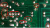
Looking at the board photo (as goldswimmerb said), a lot of the solder joints don't look good.
upload_2022-6-7_22-45-21.png
  • Many of the solder joints look like cold joints with not enough solder (and flux) to get a good and shiny solder fillet.
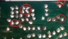
upload_2022-6-7_22-49-51.png
  • A lot of the pads have excess flux residue between the pads that need to be cleaned off with some alcohol to make sure there are no solder bridges.
  • There are some solder pads where it looks like the solder mask has been scraped off and maybe the solder is shorting to another trace.
  • The first thing I would do is take some cotton swabs (Q-tips) dipped in 99% isopropyl alcohol and clean away the rosin flux residue.
  • Then you can inspect the solder joints properly. Some of the solder joints look like they have almost no solder.
  • The solder joints should be smooth and shiny, not dull. You can add some flux to the old joints and try to reflow them or remove the solder and add fresh solder.
  • Maybe your soldering iron is not hot enough or you are not heating the board and lead with the solder tip, but heating the solder?
Here are a few more areas to check:
upload_2022-6-7_22-59-18.png
 
I'm probably confusing some 23xx models but one of them has to have the audio input connector plugged in to give the front end its ground reference. If it's unplugged the output side goes nutso!
hello.
audio input connected to p700 when tested, ground checked. :(

regards
 
Looking at the board photo (as goldswimmerb said), a lot of the solder joints don't look good.
View attachment 2587400
  • Many of the solder joints look like cold joints with not enough solder (and flux) to get a good and shiny solder fillet.
View attachment 2587407
  • A lot of the pads have excess flux residue between the pads that need to be cleaned off with some alcohol to make sure there are no solder bridges.
  • There are some solder pads where it looks like the solder mask has been scraped off and maybe the solder is shorting to another trace.
  • The first thing I would do is take some cotton swabs (Q-tips) dipped in 99% isopropyl alcohol and clean away the rosin flux residue.
  • Then you can inspect the solder joints properly. Some of the solder joints look like they have almost no solder.
  • The solder joints should be smooth and shiny, not dull. You can add some flux to the old joints and try to reflow them or remove the solder and add fresh solder.
  • Maybe your soldering iron is not hot enough or you are not heating the board and lead with the solder tip, but heating the solder?
Here are a few more areas to check:
View attachment 2587408
hello, thank you.
well, the section shown in your answer is the good one. this channel works perfectly. when is connected, relay engages, bias is 14mv and dc offset is 11mv (unit connected to DBT)
it is making me crazy.

thank you again. will double check the solder joints.
 
UPDATE ON TESTING THE BAD SIDE.
i´ve done:
-bad side feeded with the good side power conector. no changes.
-many measures taken from ECB of all the driver and pre drivers. +45v everywhere!!
-disconnected base and emiter of a couple output transistors. no changes.
-swapped some pieces from good side to the bad side: coil L701, ceramic capacitors c703 (schematics says 10pf, 50pf intalled), also new set of diferentials swaped, no changes. +45v everywhere

important: in differencial q701-q702, the bases have diferent voltages, q701 base is 45.45v, q702 base is 40.4v. so, in the emitters there are 4.5v, should be -0.6v, in consecuence -i think- in the collector of q703 have 6v. q703 emitter and case have -24v and -23v (i think not bad with dbt used)

both differential feeded through R704/R705 10K resistor wich comes from q722 diode. the curious thing is r704 has a higer voltage than r705. of couse i changed along with r706 (680omh) with new ones. no changes in the problem

sFQFxyC.jpg


i´ll keep updating until this beautiful unit were exorcised.
 
Last edited:
-many measures taken from ECB of all the driver and pre drivers. +45v everywhere!!
  • Maybe one of the output transistors has a junction short or has a damaged insulator. Can you pull-out Q001, Q002, Q003, & Q004 then recheck to see if you still have 45v at the board pins.
  • I would suggest that you post the whole P700 schematic with the measured voltages written-in and maybe someone can offer a suggestion.
 
Last edited:
Hello.

All this time absent, i was working on The unit
I can get a 2285b P700. So, i'm using it.

At this day I could't find the problema in the old p700.
 
Last edited:
This might be me, but even if it took me two weeks headscratching and misery, I had to know what the issue was on my amp. :jump:

Whatever you do, don't throw it away just now.
 
Back
Top Bottom