• The move to the new server is done. There are some software and database maintenance updates in process. This has us passing the hat around to help out. We appreciate any donations. Seriously, even a dollar helps. The payment page may be found here - https://www.audiokarma.org/support.html

5000x with original 1040-1 boards - to new 6013 “Help”

touchdownT

New Member
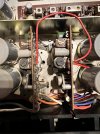
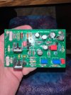
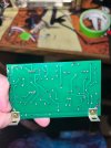
5000X with original f-1040-1 boards here. Have a set of bonzoro boards rev d f-6013. Coming into a couple issues with the new boards.

Where do I connect power leads to the reproduction f-6013 from 1042-1 diodes stack.

Originally DC+ went to the output cap and DC went directly the the 1040 board and was jumped to the other 1040 board.

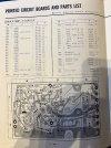
I have original schematic and service manual with the 5000x with the 1041.Have read over bonzoro instructions and the service update.

Also, want to verify the service update says to cut two wires. Can the wire from the power caps be removed from this as well then?
  1. Cut the gray and blue leads which connecting 18kS
    (RO33, R034) on the terminal with the F-1040.

Hopefully someone has had this same problem and can give me some insight.

Thanks!
 

Attachments

  • IMG_9836.jpeg
    IMG_9836.jpeg
    59.4 KB · Views: 21
  • IMG_9694.jpeg
    IMG_9694.jpeg
    240.8 KB · Views: 24
  • IMG_9692.jpeg
    IMG_9692.jpeg
    333.7 KB · Views: 26
  • IMG_9804.jpeg
    IMG_9804.jpeg
    200.6 KB · Views: 27
  • IMG_9828.jpeg
    IMG_9828.jpeg
    188.1 KB · Views: 26
  • IMG_9827.jpeg
    IMG_9827.jpeg
    264.7 KB · Views: 23
Last edited:
Register to hide this ad
Also, want to verify the service update says to cut two wires. Can the wire from the power caps be removed from this as well then?
  1. Cut the gray and blue leads which connecting 18kS
    (RO33, R034) on the terminal with the F-1040.
Yes you can remove everything if you want.

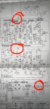
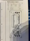
The "B" voltage in the schematic image goes to the indicated point on the driver board image below. It comes from the "DC" terminal of the diode stack board.

The red wire from front to back is not used for your application. The 5000x has that separate filtered supply for the front end of the driver board.

6013.jpg
 
So don’t jump pins 1 to 12 from fuse. DC off 1041-1 to point 12 on 6013 and jumped to other 6013 point 12, DC plus stays on cap?
 
So don’t jump pins 1 to 12 from fuse.
Correct, no jumper. Pin 12 on the new boards goes directly to the "DC" point on the F-1042 board. You can run one wire from the F-1042 to each board ora single wire and jump one board to the other.

Pin 1 on the new boards connects to the wires from the fuse holder.

The "DC +" from the F-1042 does not change. It connects to the main filter caps and the fuse holders.
 
right channel output transistors taken out. Both fuses in, dim bulb
Ah, good - getting somewhere. Check all your OPT’s. If good, look for a mounting fault that had one or more shorted to the heatsink. Correct that and bob’s yer uncle. If one or more OPT’s is bad, replace. And bob’s still yer uncle.
 
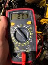
I’ve narrowed it down to one transistor causing the short. Transistor measures ok. Looks seated well using a sil pad. Not sure what I’m missing here
 
I’ve narrowed it down to one transistor causing the short. Transistor measures ok. Looks seated well using a sil pad. Not sure what I’m missing here
Confirm the wiring between the transistor socket and the new board is correct and without power on check for continuity between the case of the transistor and the chassis.
It does not take much of a burr to punch through a sill pad.
 
Confirm the wiring between the transistor socket and the new board is correct and without power on check for continuity between the case of the transistor and the chassis.
It does not take much of a burr to punch through a sill pad.
 

Attachments

  • IMG_9998.jpeg
    IMG_9998.jpeg
    224.5 KB · Views: 7
Back
Top Bottom