• The move to the new server is done. There are some software and database maintenance updates in process. This has us passing the hat around to help out. We appreciate any donations. Seriously, even a dollar helps. The payment page may be found here - https://www.audiokarma.org/support.html

5000x with original 1040-1 boards - to new 6013 “Help”

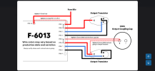
I can’t remember if this has a complimentary output or a Quasi-complimentary output. Are we certain the OPT’s are located correctly?
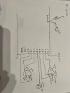
This is how it’s wired up. I found img 9853 on a thread on this subject. Through searching and advice from this post I brought the DC off 1042-1 board to the 12 pin on the 6013 board instead of to the fuse.

New caps and transistors. I don’t know what would be wired incorrectly as I followed this and triple checked.

1041 to 6013 had some other things involved from the bulletin update from Sansui as well that was done.

I appreciate the help on here. And being completely honest this is the deepest I have ever been into a vintage receiver. It was my grandfathers, he bought new in the Navy. Hasn’t worked since the 70s and sat in the original box. Been a paper weight for a couple years. Feel like I’m back to square one here.
 

Attachments

  • IMG_9853.png
    IMG_9853.png
    73.2 KB · Views: 15
  • IMG_9991.jpeg
    IMG_9991.jpeg
    169.3 KB · Views: 15
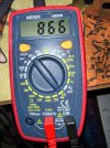
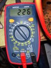
Not 100% sure what that meter image is showing me? Continuity check between the transistor case and the chassis I assume?

If that is indeed what is going on, lets go a little deeper. Again with the power off and this time pull both the back panel amp fuses.

Set your meter for the low ohms scale (looks like you have 200). Black lead to chassis.

With the red lead start with the working channel and touch the cases (collector) of the output transistors and note the values, then do the same thing to the non-working channel.
 
Last edited:
Not 100% sure what that meter image is showing me? Continuity check between the transistor case and the chassis I assume?

If that is indeed what is going on, lets go a little deeper. Again with the power off and this time pull both the back panel amp fuses.

Set your meter for the low ohms scale (looks like you have 200). Black lead to chassis.

With the red lead start with the working channel and touch the cases (collector) of the output transistors and note the values, then do the same thing to the non-working channel.
My crappy MM leaves a lot to be desired I have a new one on order. Don’t think I’m getting a proper reading
 
In the picture your MM is set to the diode/continuity test and judging by the dial it should make noise if there is continuity. If you put the leads together on that setting and get no sound something may be wrong, though it may just be the sound function.
Set it to the 200 ohm spot. Touching the leads together would probably show a bit less than one ohm. On my cheap MM's the reading without the leads touching is 1, on my better MM with no leads touching it reads OL. Just a basic way to check the MM ohm section. I've used cheaper MM's than yours with success.
 
In the picture your MM is set to the diode/continuity test and judging by the dial it should make noise if there is continuity. If you put the leads together on that setting and get no sound something may be wrong, though it may just be the sound function.
Set it to the 200 ohm spot. Touching the leads together would probably show a bit less than one ohm. On my cheap MM's the reading without the leads touching is 1, on my better MM with no leads touching it reads OL. Just a basic way to check the MM ohm section. I've used cheaper MM's than yours with success.
200 ohm spot. Positive on collector, negative to chassi I am getting 1.
 
Is 1 what you get when the leads are disconnected? If so that's maybe your MM's out of range (infinite) indication, i.e. open circuit.
 
when I go set the meter to continuity/diode check. this is what I am getting with positive on the screw of each transistor and negative to chassi.
 

Attachments

  • IMG_0021.jpeg
    IMG_0021.jpeg
    307.7 KB · Views: 4
  • IMG_0022.jpeg
    IMG_0022.jpeg
    316.6 KB · Views: 4
  • IMG_0023.jpeg
    IMG_0023.jpeg
    300.2 KB · Views: 4
  • IMG_0025.jpeg
    IMG_0025.jpeg
    323.3 KB · Views: 4
I am not sure why you're measuring at the screws and not sure why you are using the diode check setting. Maybe someone else has a clue.
Basic method for the output transistors: Probe to case, other probe to chassis, MM dial set to 200 ohm. IIRC there are four screws where the output transistors sit. Two are in circuit with the collector of the transistor, these would read the same as the transistor case. I believe the other two are just to hold things to the "backside" of the heatsink and themselves just connect to ground.
 
You are correct in that it, they physically connect to the case and screw into a connection on the insulating board on the opposite side of the heatsink from the transistor. It is just there are two other screws that screw into the heat sink to hold the insulating board the heat sink. This is how the cases are mounted without shorting. What is the reading from the cases to the chassis?
 
That is exactly what you want. It means the transistor is not shorted to the heatsink. Repeat for all outputs.
If you get a bright bulb on one channel something is probably shorted to ground, quadruple check every connection.
Took me months to find a bad ground on my first unit. While your problem is different I just want to point out that finding this stuff can be difficult, particularly if you are unfamiliar with the process.
 
are any of the output transistors showing as short? Is your DBT bright with the fuses out? Unlikely but if so look for the sort going back to the power supply.
If not bright with the fuses out start tracing from the fuse output through the amp circuits.
 
Back
Top Bottom