

You are using an out of date browser. It may not display this or other websites correctly.
You should upgrade or use an alternative browser.
You should upgrade or use an alternative browser.
6EM7 / 2A3 build
- Thread starter SS904
- Start date
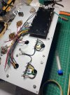
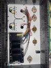

That fine-grain pebble finish must be unique to FPE. I recognized it the minute I saw your photos. The panels I bought from them years ago for my 211s look exactly the same.
Jack
Jack

Similar to; Jeet? (Did you eat)Git ot! (as we used to say in Pittsburgh, translation, "Get out!"). That's amazing.


My plan was to use a star ground with everything, except power ground, going to the single point. I have the ground points mounted where the OPT commons are connected. It's worked for me before, but on my last build I did use a buss for the RCA inputs, input cable shield and a pair of volume controls. This one is a bit simpler.I would urge you to use a "ground bus" and only ground it at one point to the chassis (earth) ground. I see you have tied both OPT commons together to the chassis already.

FWIW: Morgan Jones asserts that each output transformer ground should be connected to its respective input tube's cathode ground. If feedback is used, the feedback wire from the output transformer should be a twisted pair with the ground wire (he says shielded) and the two wires would attach to the positive end of the cathode resistor and it's ground.
Making this change.FWIW: Morgan Jones asserts that each output transformer ground should be connected to its respective input tube's cathode ground. If feedback is used, the feedback wire from the output transformer should be a twisted pair with the ground wire (he says shielded) and the two wires would attach to the positive end of the cathode resistor and it's ground.
Reading your quote I'm assuming the "output transformer's respective input tube" is the 2A3, in this case. Since I tend to over think things, I just want to be sure when you say input tube you're referring the 2A3 and not the driver stage...
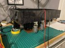
First design error challenge. Didn't leave enough room between the driver tubes. Was planning to build the circuit on two tag strips. Nope. Had to stuff it on one longer strip. Fits and will work. Not very serviceable though. If I ever need to change a component, it will a pain. Power supply is done. Waiting to wire the rest of the sockets before mounting the top plate to the chasses and connecting power.

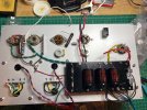
Powered up with a rectifier in place. Everything is good. No smoke, voltages are where they need to be. Tomorrow the chassis goes together. Power connector, RCA's and speakers will be wired and testing will begin. Need to figure out what I need for a B+ drop resistor after full load is applied.
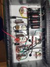
A little messy compared to what I had in my head, but it will work.
Edit... Realized I didn't wire the center tap to my voltage divider for the elevated 6.3VAC filaments. Will get that too. Measuring around 52VDC at that tap. Should be good for the 6EM7s.
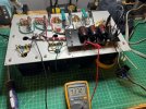
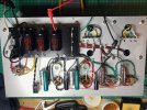
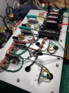
A little messy compared to what I had in my head, but it will work.
Edit... Realized I didn't wire the center tap to my voltage divider for the elevated 6.3VAC filaments. Will get that too. Measuring around 52VDC at that tap. Should be good for the 6EM7s.
Last edited:
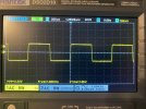
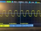
Up and running, but still need to do some testing. I have ARTA on my laptop and will dig in to that tomorrow. Just used the meter and scope today. Clips about 3.8W at 1K Hz. About the same at 20 Hz and 20K Hz. Square waves look good. Dirty distortion check with my scope's FFT display is encouraging. Some 2nd order, no other peaks.
Hooked up my "shop" bookshelves feeding it with a Bluetooth adapter and my phone. No hum sounds clean top to bottom. Looking forward to connecting them to my Fortes.
Some tweaking today. I had 850 Ohm cathode resistors installed and was getting 34 mA plate current. Swapped in my lowest 20W resistors, 700 Ohm both measuring 699. 288V on the plate gives me about 41mA. Maybe a bit cool? Isn't 50 mA a good target here?
I will order some smaller 20W cathode resistors and see what happens.

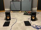
Hooked up my "shop" bookshelves feeding it with a Bluetooth adapter and my phone. No hum sounds clean top to bottom. Looking forward to connecting them to my Fortes.
Some tweaking today. I had 850 Ohm cathode resistors installed and was getting 34 mA plate current. Swapped in my lowest 20W resistors, 700 Ohm both measuring 699. 288V on the plate gives me about 41mA. Maybe a bit cool? Isn't 50 mA a good target here?
I will order some smaller 20W cathode resistors and see what happens.

For SE 2A3 amps, I always use 750/25W for cathode resistors. Other operating points are acceptable too if you know where you are on the load line.Up and running, but still need to do some testing. I have ARTA on my laptop and will dig in to that tomorrow. Just used the meter and scope today. Clips about 3.8W at 1K Hz. About the same at 20 Hz and 20K Hz. Square waves look good. Dirty distortion check with my scope's FFT display is encouraging. Some 2nd order, no other peaks.
Hooked up my "shop" bookshelves feeding it with a Bluetooth adapter and my phone. No hum sounds clean top to bottom. Looking forward to connecting them to my Fortes.
Some tweaking today. I had 850 Ohm cathode resistors installed and was getting 34 mA plate current. Swapped in my lowest 20W resistors, 700 Ohm both measuring 699. 288V on the plate gives me about 41mA. Maybe a bit cool? Isn't 50 mA a good target here?
I will order some smaller 20W cathode resistors and see what happens.
What is your B+ going into the OPT B+ lead? The Sovtek 2A3's are very similar to the JJ2A3-40, but my estimation is they have a plate dissipation of approximately 30W not 40W.
I usually run the Sovtek 2A3's between 250V~285V (voltage across tube measured from plate to cathode) with 45V~50V bias. This is with a 750 ohm cathode resistor. Since you have a 700 ohm resistor your results will vary slightly.
I would shoot for at least 60mA of idle current through the tube and probably something around 65mA will be where you end up (just a guess).
Edit: I just read where you will be using the EH2A3, not the JJ2A3-40. In this case, you should have approximately 250V across the tube with 60mA bias or as close as you can get with the 700 ohm cathode resistor. The EH2A3 is probably a rebrand of the Sovtek 2A3 and it will more than likely have increased plate dissipation like the Sovtek 2A3.
This is the part where I try to mentally place most of the major parts in the build before I solder. I draw the sockets/chassis layout out on a piece of paper and then pencil in the parts as if they were soldered. In this manner, I know everything will "fit" and be placed for easy service before the soldering iron even gets turned on.First design error challenge. Didn't leave enough room between the driver tubes. Was planning to build the circuit on two tag strips. Nope. Had to stuff it on one longer strip. Fits and will work. Not very serviceable though. If I ever need to change a component, it will a pain. Power supply is done. Waiting to wire the rest of the sockets before mounting the top plate to the chasses and connecting power.
Works most of the time, but you know how it is to go back and make it "more" perfect.
Woke up this morning knowing my mistake... If you look at my math above for plate current, it just makes no sense. That's because I was taking plate voltage and dividing by cathode resistor. I should have walked away when I got it powered up with no problems rather than pushing forward. With the 700 ohm resistors I was closer to 74 mA. Cathode was dropping about 52 VDC.For SE 2A3 amps, I always use 750/25W for cathode resistors. Other operating points are acceptable too if you know where you are on the load line.
What is your B+ going into the OPT B+ lead? The Sovtek 2A3's are very similar to the JJ2A3-40, but my estimation is they have a plate dissipation of approximately 30W not 40W.
I usually run the Sovtek 2A3's between 250V~285V (voltage across tube measured from plate to cathode) with 45V~50V bias. This is with a 750 ohm cathode resistor. Since you have a 700 ohm resistor your results will vary slightly.
I would shoot for at least 60mA of idle current through the tube and probably something around 65mA will be where you end up (just a guess).
Edit: I just read where you will be using the EH2A3, not the JJ2A3-40. In this case, you should have approximately 250V across the tube with 60mA bias or as close as you can get with the 700 ohm cathode resistor. The EH2A3 is probably a rebrand of the Sovtek 2A3 and it will more than likely have increased plate dissipation like the Sovtek 2A3.
Worked on it most of the morning and wound up back with the 850s (each measuring 841 ohms). With the 850s I'm still a little hot for NOS tubes at 63mA and 18W dissipation, but I'll be using the EXH and the JJ 2A3-40s. Probably the JJs mostly, but I haven't tested those yet. What I really need to do is add a dropping resistor between the 2A3 plates and B+. My B+ is 350VDC. I landed there because the schematic for the 6EM7 driver calls for it and that driver seems to be working perfectly.
Rechecked max output, square waves and distortion using my FFT display. Things look great to me in those areas. My laptop with ARTA is busy streaming Amazon Music at the moment, so I'm walking away for today before I do something else dumb!
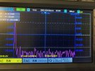
FFT display at 1W left ch, right is the same. This is with the EHX tubes and my noisy signal generator with some built in distortion.
The 6EM7/6EA7 will work fine at 300~325V too. The recommended 350V was for driving a 300B with max signal output. Use a 10 or 20uF cap and dropping resistor from the OPT B+ to feed the 6EM7.
I use the same Ohmite Brown Devil resistors as you have there. I bought a bunch of 750/25W a long time ago. I use 1k/20~25W for 300B's.
To drop your 350ish B+ to around 300~310V, I calculate you'll need a 1.8k/5W resistor.
I use the same Ohmite Brown Devil resistors as you have there. I bought a bunch of 750/25W a long time ago. I use 1k/20~25W for 300B's.
To drop your 350ish B+ to around 300~310V, I calculate you'll need a 1.8k/5W resistor.
Last edited:
Thanks. Good to know 350VDC to the driver isn't a hard requirement. I'll up my dropping resistor to tame overall B+ and see where I land on the power tube operating point.
But for now, screw it! I'm letting it cook for the rest of the night and it sounds great. Some 60HZ hum at first that I wasn't hearing with my bookshelves speakers, but present on the Fortes. 98% of that was tuned out with the filament balance pots. Not bothersome at all.
Need to finish the bottom plate and get some proper feet on it too. This is one heavy beast. Don't plan to move it too many times!
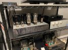
But for now, screw it! I'm letting it cook for the rest of the night and it sounds great. Some 60HZ hum at first that I wasn't hearing with my bookshelves speakers, but present on the Fortes. 98% of that was tuned out with the filament balance pots. Not bothersome at all.
Need to finish the bottom plate and get some proper feet on it too. This is one heavy beast. Don't plan to move it too many times!