• The move to the new server is done. There are some software and database maintenance updates in process. This has us passing the hat around to help out. We appreciate any donations. Seriously, even a dollar helps. The payment page may be found here - https://www.audiokarma.org/support.html

A 2330B rebuild

klamsoss

Be willing to fail and try again.
I have this monster of a receiver on the bench now (still need to tidy up the clipping on the 1060, but it's pretty much good to go) and am preparing to tear into it. My goal is to replace all the electrolytics, set whatever levels need to be set for best performance within the pre and power amp sections, and not interfere with anything in the tuner sections, which seem to be working fairly well.
I have bookmarked a few threads where others have provided very helpful guidance. I'll try not to repeat questions here which are already addressed in those threads. I'll be posting pictures soon.

Observations and questions:
1. The printed boards in this aren't the easiest to get to. I was able to do the 1060 without having to take anything fully out of the chassis, but that doesn't look like it'll work here. Photos photos and more photos should help me keep track of everything.

2. There is no main power filter capacitor in this, that I can see. Can anyone advise me on how I can easily and efficiently drain all the caps in the receiver before I start slinging solder? I'd really like to not have to go through each one individually if possible.

3. There are a lot of electrolytics in the tuner section. Can anyone tell me from their own experience if replacing these will impact the alignment in a meaningful way?
 
Register to hide this ad
The power supply board isn't fun on this model. Couple transistors and the relay need replacing there.

It's literally not possible to drain all caps, or even needed. And there are two main filter caps.....right in front of the transformer.

I'd leave the tuner. PIA to get to, and no reason to if it's working.
 
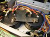
I would use a clip lead to short from the capacitor lugs with the White wires to the chassis, then short from the capacitor lugs with the Red wires to the chassis. Notice that there are two capacitors to drain.
2330B filt (2).jpg

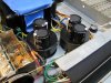
To replace the NLA 'dual' filter capacitors with single ones, I do this:
2330B filt (5).JPG

None of the electrolytic capacitors affect the tuning.

YMMV.
Tom

Tom
 
I had assumed (or read somewhere... hard to know) that the two double caps in front of the xfo were output coupling caps.

Tom, many thanks for the great input!
I was hoping that the 'lytics could be replaced without affecting the alignment. For tube tuners there is often a need to realign when you replace certain tubes, or if you change any values of anything. I don't know all that much about solid state gear, though, so this is a really good piece of info to have, especially because I have a 2325 in the queue.

What is the material filling the space in those big cans? I really like how you have that set up and it seems easier than "restuffing", which is what I had planned to do.

Ivan, do you have a particular set of transistors you like to replace on this unit? I know the 458 transistors all need to go, and the 2sc1000 can go too, but aren't necessarily critical. I'm not sure if I got the right relay for it or if I got the one I will need for the 2325 that is coming up after this one.
 

Attachments

  • 20200319_193920.jpg
    20200319_193920.jpg
    56.8 KB · Views: 90
I had assumed (or read somewhere... hard to know) that the two double caps in front of the xfo were output coupling caps.

Tom, many thanks for the great input!
I was hoping that the 'lytics could be replaced without affecting the alignment. For tube tuners there is often a need to realign when you replace certain tubes, or if you change any values of anything. I don't know all that much about solid state gear, though, so this is a really good piece of info to have, especially because I have a 2325 in the queue.

What is the material filling the space in those big cans? I really like how you have that set up and it seems easier than "restuffing", which is what I had planned to do.

Ivan, do you have a particular set of transistors you like to replace on this unit? I know the 458 transistors all need to go, and the 2sc1000 can go too, but aren't necessarily critical. I'm not sure if I got the right relay for it or if I got the one I will need for the 2325 that is coming up after this one.
The relay is a MY4-02-DC24.
I replace the TO-220 power transistors with TIP31/32C, otherwise there isn't much in this unit except like you said the 2SC1000's if you want to.
 
The capacitor 'pucks' are made by an associate with a 3D printer.
The dual capacitors are, in fact, power supply filters. Most high power amps and receivers use direct coupling to the speakers, no output coupling capacitors, the 2330B is no exception.

Tom
 
Made some progress on this last night but I made a stupid mistake. No harm done... YET...

I'm working on the PU01 speaker selector/switch board.
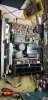
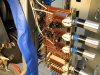
The pictured green capacitor is a substitute for one that isn't on the schematic or parts list. But there was definitely a 10uF 16V elna polar cap between JU15 and JU18. I did a dumb thing and cut it out without taking a picture and now I don't know what the polarity orientation was. My thought was to replace it with a bipolar cap of the same value (non-polar films are too large for this area). Will that screw anything up?

Before you answer...

Notice in the picture that CU03 isn't present. I'm 95% sure it wasn't there when I started, even though there is solder on the trace side of the board (it doesn't look like it has ever been remelted, and I am really good about going one piece at a time). CU03 is listed in the specs as a 10uF 16V cap, just like the mystery one between JU15 and JU18. Those nodes aren't the same as the nodes where CU03 connects, though, at least not directly. I've checked the marantz schematic mistakes, and looked at other 2330B rebuilds, and I can't find a good picture of that board anywhere, and I'm not sure wha, if any other models use the same board. Does anyone have a 2330B or pictures from a rebuild that show this board? I can't believe I didn't take a picture. Not like me at all.
 

Attachments

  • 20200329_114808.jpg
    20200329_114808.jpg
    41.7 KB · Views: 82
AHHHH!!! Thank you guys so much!!! You're awesome!
I see you're both also missing CU03 (so I'm not crazy!) and that you've got the unidentified cap across the same J points that I do!

I can't tell for sure but it looks like the negative side of that floating cap is going to JU14. Any reason not to just solder in the bipolar cap I have as a place holder, and call it a day?
I was under the impression that the orientation of bipolar caps, like film and ceramic, is essentially irrelevant (quibbles about outside foils and theoretical sound differences aside) and that substituting one in place of a polar cap is no problem. But I've actually never used bipolar caps.
 
And there are two main filter caps.....right in front of the transformer...

I always replace the main filter caps and on the 2285b, 2330b, 2385, 2500, 2600 I prefer to open the cans, remove contents and 'stuff' new capacitors inside. By opening within the clamp area when re-assembled the can looks original and I just like to retain that original appearance :)

1.jpg

2.jpg

3.jpg

4.jpg
 
Filter caps are next. I don't want to get too far ahead of myself without doing a listening test. So I'm looking to figure out if that bipolar cap is okay as a replacement for the polar one that had been there. Then button it up and make sure everything is as good or better than it was before.
I've done the electrolytics in the tone controls, power supply (except the big filters), and half the tuner board. Waiting on the new relay for the power supply to be delivered.

Originally I was going to replace any transistors that have newer equivalents that might perform better, but I think I'll leave them as-is unless I identify an issue or they are widely known to go bad (like the 458s in the 1060 I just worked on). I'm not making money, and this is more for learning and helping a buddy out than attaining all-out perfection.
 
Last edited:
The relay is a MY4-02-DC24.
I replace the TO-220 power transistors with TIP31/32C, otherwise there isn't much in this unit except like you said the 2SC1000's if you want to.


I don't know what TO-220 transistors you are talking about. I don't see anything in the parts list called a TO-220. This is probably something super obvious that I just don't understand due to my lack of knowledge about solid state gear...:dunno: can you give me more info? Either a part number from the service manual or the transistor description (i.e. 2scXXXX). I want to make sure I know what I'm doing here...
 
I think he was referring to the medium power transistor(s) on the power supply. The part number would be 2SD331,2, or 3.
 
I don't know what TO-220 transistors you are talking about. I don't see anything in the parts list called a TO-220. This is probably something super obvious that I just don't understand due to my lack of knowledge about solid state gear...:dunno: can you give me more info? Either a part number from the service manual or the transistor description (i.e. 2scXXXX). I want to make sure I know what I'm doing here...
TO-220 is a case size. Google is your friend.
 
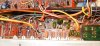
I've been back at work on this. Waiting for the relay, I got impatient. I ended up doing pretty much all of the electrolytic caps through the whole thing, without any step by step testing :confused:. I was, however, much more diligent about taking pictures, going one part at a time, and triple checking everything. The main power amp board is the only thing I haven't yet touched, and I will definitely test it out before starting on that.

First up, we have the main power supply caps.
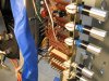
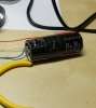
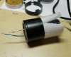
For these, I restuffed the cans using 2x 6800uh 80V each (nichicon low-ish ESR. not sure what series...). I measured ahead to make sure they would fit. Since they wouldn't fit side by side like in Velox's post, I taped them together top to top, wired a positive to a negative, and extended the leads. See Pic 1. The basic setup, as you can see in the pic, is that I attached a lead (blue) to the negative side of cap 1, then ran the white wire from the negative side of cap 2 over to the positive side of cap 1 and left a tail there so I can wire that to ground. Then on the positive side of cap 2, I attached the red wire and ran that down the other side so the whole shebang can be packed into the old cans and all 3 contacts can come out the bottom. I'm pretty sure both of them were done this way, but not 100% sure. MISTAKE. :whip:I'm not risking it. Gonna pull it out and double check the polarities before I send any power to this thing.

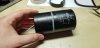
To cut open the cans, I used a hacksaw. The first one was rough. I didn't realize that you don't have to cut the thing in half straight through... you can just cut through the aluminum can around the outside. For the second, I got a much neater cut. I used some scrap wood to whip up a makeshift wedge/block to hold the can in a miter box, and I rotated the can as I went, so my blade never went more than a few mm in. Just enough to cut through the casing. MUCH easier. Anyway, see pic 2 for the beginning of the surgery.
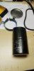
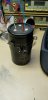
I used a 14in pipe wrench to twist the guts out of the cans. Worked very well. Almost all of it came out in a big chunk and I just had to use a screwdriver to remove a small amount of remaining waxy coating from the inside of the top of each can.I drilled a few holes in the phenolic plate at the bottom of the cans for the wires to come out of. Tip for folks out there: do this outside or at least in a bathroom with the vent fan on. When you cut/break phenolic resin, it releases gasses that smell terrible and are terrible for you. If I had it to do over again, I wouldn't have broken the original tabs off the bottoms of the cans. I would have left at least the "A" and "B" tabs in place to use as solder lugs for the new wires. Pics 3 and 4 show various stages of the restuffing work. I had some 1/2" open cell foam packing material that came with something or other. This stuff worked really perfectly to line the cans and hold the new caps in place. Once the new guts were installed, I used black duct tape to stick the cans back together. The clamps help hold the two halves in place, as well. See pics 5 through 7.

Again, I wish I had looked back at Velox's post here and thought to leave at least the two tabs for the non-ground wires (red and blue in my reconstruction). That might have made me be more careful to double check the polarity of my reconstruction. I also wish I had planned to color match the positive and negative "terminal" wires coming out of the restuffed cans with the red and white wires inside the amp. Lessons for next time.:naughty:

I'll post a pic of the final installation after I verify the polarity of the restuffed cans.

While I was working on this, my x-tronic 3020 soldering iron bit the dust. I took it apart but couldn't identify the problem. it isn't the switch, or a blown fuse, and there is no visible scorching or blown components. It's only 9 months old, and although it has a 3 year warranty, I got it on Amazon so I'm not sure how likely I am to get a replacement. (still gonna try, though)
Anyway, rather than get another potentially short-lived iron, I decided to go with something that is sold locally and a bit more serious. I checked out Dayton Audio/Parts Express and ended up getting the Stahl DSDS Soldering Station. It has an iron and a desoldering gun, both with digital temperature control. The reviews were positive and it has a year warranty so I took the $175 risk figuring that with the dealer being local-ish (35 minutes away), I would at least have an easier time of it if there ends up being a warranty claim. I also wasn't prepared to shell out $100ish for a hakko iron, and another $400ish for the hakko desoldering gun.
Initial impressions are that this is a good piece of equipment. The desoldering gun works pretty well in my first 5 or 6 tests. Like the desoldering pumps I have used, you do have to clean the suction tube out every couple of uses, but the station comes with 3 little poker tools that makes it pretty easy. Certainly easier than disassembling the pencil style hand pump I've used for the last year. The suction is good, and the tip of the gun heats up reasonably quickly. The iron itself heats up fast and seems to maintain temp reasonably well. It comes with just the standard pencil type tip for the iron, so I wish I had ordered the $7 set of interchangeable tips to go with it. I've grown quite fond of using a small, flat wedge shaped tip. That shape seemed to hold and transfer heat better than the standard pencil style tip on my x-tronic. I suspect that a similar tip for this Stahl iron will have comparable results. The only knock I have on the setup is that there's no solder spool holder. It took a bit of work, and minor disassembly of the new Stahl DSDS, but it wasn't too difficult to just attach the one from the x-tronic to the side of the DSDS.

Next steps for the 2330B are to double check the polarity in the one can, put the new transistor and relay on the power supply board, and give it a listen.
If all is well, I'll finish off the main power amp board and button it all up. If all is NOT well, you can be sure I'll be back here either documenting the issue and fix, or soliciting input from the AK braintrust.

 

Attachments

  • Marantz 2330B restuff Pic 1 new caps.jpg
    Marantz 2330B restuff Pic 1 new caps.jpg
    74.5 KB · Views: 116
  • Marantz 2330B restuff Pic 2.jpg
    Marantz 2330B restuff Pic 2.jpg
    76.3 KB · Views: 115
  • Marantz 2330B restuff Pic 3.jpg
    Marantz 2330B restuff Pic 3.jpg
    101.3 KB · Views: 113
  • Marantz 2330B restuff Pic 4.jpg
    Marantz 2330B restuff Pic 4.jpg
    66.5 KB · Views: 111
  • Marantz 2330B restuff Pic 5.jpg
    Marantz 2330B restuff Pic 5.jpg
    47.9 KB · Views: 108
  • Marantz 2330B restuff Pic 6.jpg
    Marantz 2330B restuff Pic 6.jpg
    46.4 KB · Views: 104
  • Marantz 2330B restuff Pic 7.jpg
    Marantz 2330B restuff Pic 7.jpg
    50.6 KB · Views: 110
Last edited:
Update:
I did, indeed do both of the restuffed cans the same way. No issues there. Also, the desoldering gun works quite well. I am very pleased with it and hopeful that it lasts a good long time.

Sunday, after I replaced the relay on the P800 board, I decided to give this thing a try. I got a pair of junker headphones and plugged those in, hooked up some dummy loads to the main speaker outputs, and hit the power button. No sizzles, no pops, no drama. I selected FM stereo and tuned into one of my favorite radio stations (WMKV, you NEED to look up their streaming broadcast if you like jazz, big band, swing, etc). Reception was pretty good. Really, quite good. I was surprised and pleased with the tone. After doing the 1060 I was honestly angry at how bad it sounded. It took a good 10 hours of burn in before I really got a taste of how it was going to sound. THIS, on the other hand, sounded pretty good right off the bat.

Problems:
the "Multipath" button doesn't work. Seems like a broken switch - the button won't stay in. Since it's not exclusively necessary, I may leave it as-is. The guy who is getting this unit probably won't use the tuner portion much anyway, and finding exactly the right switch, then digging back into it so I can install it is probably not worth the effort. If anyone has some good insight on this, let me know.

There is a light out behind the display, you can see in the pic. I don't know how to replace that or what bulb/LED/wizardry is needed. I really WOULD like to fix this aspect of the unit because this thing looks so damn cool when lit up. In the coming days, I'll be scouring AudioKarma for info on how to fix this issue, but if anyone cares to weigh in on it now, I welcome the input!

Lastly, the signal strength meter doesn't seem to work very well. It's not dead, it just doesn't move much. I'm wondering if it's related to the multipath switch not working, since I know multipath has something to do with aligning the antenna for best reception...? Since it doesn't materially impact the function of the unit for its primary use, I'll probably not worry about that one either, unless someone has some brilliant input.

I'm pleased with the results so far. Tickled that it sounds so good right away, and looking forward to breaking it in and seeing where it ends up! Also, it's cool that it has two phono inputs. I'm always a fan of that since I have at least a couple turntables around at any given time. I may get the chance to do a Rega P1 vs Pro-ject Debut Carbon DC showdown here soon. I have the Pro-ject, and my dad has the Rega. I got him a new cart for xmas, and will be installing it in the next week or two.

Anyway, a few more caps to replace on the main power board, and then I'm going to try and find a comprehensive list of 'The Usual Suspects' when it comes to faulty transistors. Just want to make sure this pleases for years to come. After that, I just have to get my big list of records together for payment. :D
 

Attachments

  • 20200503_202441.jpg
    20200503_202441.jpg
    90.2 KB · Views: 46
Last edited:
Update:
I did, indeed do both of the restuffed cans the same way. No issues there. Also, the desoldering gun works quite well. I am very pleased with it and hopeful that it lasts a good long time.

Sunday, after I replaced the relay on the P800 board, I decided to give this thing a try. I got a pair of junker headphones and plugged those in, hooked up some dummy loads to the main speaker outputs, and hit the power button. No sizzles, no pops, no drama. I selected FM stereo and tuned into one of my favorite radio stations (WMKV, you NEED to look up their streaming broadcast if you like jazz, big band, swing, etc). Reception was pretty good. Really, quite good. I was surprised and pleased with the tone. After doing the 1060 I was honestly angry at how bad it sounded. It took a good 10 hours of burn in before I really got a taste of how it was going to sound. THIS, on the other hand, sounded pretty good right off the bat.

Problems:
the "Multipath" button doesn't work. Seems like a broken switch - the button won't stay in. Since it's not exclusively necessary, I may leave it as-is. The guy who is getting this unit probably won't use the tuner portion much anyway, and finding exactly the right switch, then digging back into it so I can install it is probably not worth the effort. If anyone has some good insight on this, let me know.

There is a light out behind the display, you can see in the pic. I don't know how to replace that or what bulb/LED/wizardry is needed. I really WOULD like to fix this aspect of the unit because this thing looks so damn cool when lit up. In the coming days, I'll be scouring AudioKarma for info on how to fix this issue, but if anyone cares to weigh in on it now, I welcome the input!

Lastly, the signal strength meter doesn't seem to work very well. It's not dead, it just doesn't move much. I'm wondering if it's related to the multipath switch not working, since I know multipath has something to do with aligning the antenna for best reception...? Since it doesn't materially impact the function of the unit for its primary use, I'll probably not worry about that one either, unless someone has some brilliant input.

I'm pleased with the results so far. Tickled that it sounds so good right away, and looking forward to breaking it in and seeing where it ends up! Also, it's cool that it has two phono inputs. I'm always a fan of that since I have at least a couple turntables around at any given time. I may get the chance to do a Rega P1 vs Pro-ject Debut Carbon DC showdown here soon. I have the Pro-ject, and my dad has the Rega. I got him a new cart for xmas, and will be installing it in the next week or two.

Anyway, a few more caps to replace on the main power board, and then I'm going to try and find a comprehensive list of 'The Usual Suspects' when it comes to faulty transistors. Just want to make sure this pleases for years to come. After that, I just have to get my big list of records together for payment. :D
The multipath button isn't supposed to stay in, it's behaving correctly.

For lights just use 8V LED fuse lamps. Very easy to install, especially on this model. The plastic will likely break, but easy to secure again.

I would check grounding for the meter.
 
Back
Top Bottom