

You are using an out of date browser. It may not display this or other websites correctly.
You should upgrade or use an alternative browser.
You should upgrade or use an alternative browser.

klamsoss
Be willing to fail and try again.
Quick question:
The manual indicates using a VTVM to adjust the idle current for this. My VTVM doesn't go down to the mV scale level, but my Fluke 87V DMM sure does. In fact, it has a setting for mV measurement.
I know that DMMs usually have a slightly lower loading than VTVM meters (10 Mohm vs 11 Mohm, if I'm not mistaken), and that in some cases, a 100k or greater resistor can/should be used to compensate for that loading. Is this something I need to do with my Fluke when checking the idle current, given the very small value? Or just hook it up, set to mV and go to town?
The manual indicates using a VTVM to adjust the idle current for this. My VTVM doesn't go down to the mV scale level, but my Fluke 87V DMM sure does. In fact, it has a setting for mV measurement.
I know that DMMs usually have a slightly lower loading than VTVM meters (10 Mohm vs 11 Mohm, if I'm not mistaken), and that in some cases, a 100k or greater resistor can/should be used to compensate for that loading. Is this something I need to do with my Fluke when checking the idle current, given the very small value? Or just hook it up, set to mV and go to town?

klamsoss
Be willing to fail and try again.
*updated*
I think this one is pretty much wrapped up!
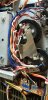
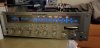
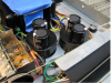
The pics are of the restuffed cans in place. As previously stated, it's definitely not as neat as it could have been.... I really wish I had left the tabs on the cans . Then I've got the tuner boar freshly outfitted with new caps and then the display with working lights. In a few places I replaced the smaller value electrolytics with films. I kept stock values, though, throughout. Only things changed were that most of the voltage ratings are higher.
Anyway, all the caps are done, a couple transistors, the relay, and then Tuesday I replaced a few of the display bulbs that were out. Finally time for a test run.
I fired it up, checked a few functions, and let it warm up for 15 minutes while I listened to Lionel Hampton on my main system. After the warm up, the idle current for the Marantz was set to 16mV +/- 0.2mV on each side and the dc offset was adjusted down to zero +/-0.2mV on each side. These are both per the manual specifications. I don't have everything I would need to do all the tuner alignments, and the tuner worked just fine before so I left that all alone. After that, I made a spot in my new home office (no more office work on the electronics bench! ) next to the desk, and hauled this big ass thing in there to hook up the test speakers. I tuned in a few radio stations to see how it sounded and liked what I heard. No notable issues once I realized that you have to actually turn the tone controls on.
I've now been listening to the radio for a few hours as I work and It sounds pretty good, I guess. Not great. It doesn't have anything like the rich tone or the excitement of my Fisher tuner/amp combo, or the smoothness of the 1060 I did recently, but it's clean, controlled, detailed... I dunno. There's nothing wrong with the sound, but it isn't interesting or exciting, really.
Admittedly, listening to it with my tiny little desk speakers (PSB mites) in nearfield isn't really the way to exercise this thing, and I also thought the 1060 sounded pretty crappy when it was freshly done. It wasn't until I had run it for 20 hours or so that the music came back into the sound. Once it has some hours on it and some real speakers, I'm thinking things will shape up. And I'm really looking forward to doing some A/B turntable comparisons with this 2 phono option! That should be a fun way to break it in.
I think this one is pretty much wrapped up!
The pics are of the restuffed cans in place. As previously stated, it's definitely not as neat as it could have been.... I really wish I had left the tabs on the cans
. Then I've got the tuner boar freshly outfitted with new caps and then the display with working lights. In a few places I replaced the smaller value electrolytics with films. I kept stock values, though, throughout. Only things changed were that most of the voltage ratings are higher.Anyway, all the caps are done, a couple transistors, the relay, and then Tuesday I replaced a few of the display bulbs that were out. Finally time for a test run.
I fired it up, checked a few functions, and let it warm up for 15 minutes while I listened to Lionel Hampton on my main system. After the warm up, the idle current for the Marantz was set to 16mV +/- 0.2mV on each side and the dc offset was adjusted down to zero +/-0.2mV on each side. These are both per the manual specifications. I don't have everything I would need to do all the tuner alignments, and the tuner worked just fine before so I left that all alone. After that, I made a spot in my new home office (no more office work on the electronics bench!
) next to the desk, and hauled this big ass thing in there to hook up the test speakers. I tuned in a few radio stations to see how it sounded and liked what I heard. No notable issues once I realized that you have to actually turn the tone controls on.I've now been listening to the radio for a few hours as I work and It sounds pretty good, I guess. Not great. It doesn't have anything like the rich tone or the excitement of my Fisher tuner/amp combo, or the smoothness of the 1060 I did recently, but it's clean, controlled, detailed... I dunno. There's nothing wrong with the sound, but it isn't interesting or exciting, really.
Admittedly, listening to it with my tiny little desk speakers (PSB mites) in nearfield isn't really the way to exercise this thing, and I also thought the 1060 sounded pretty crappy when it was freshly done. It wasn't until I had run it for 20 hours or so that the music came back into the sound. Once it has some hours on it and some real speakers, I'm thinking things will shape up. And I'm really looking forward to doing some A/B turntable comparisons with this 2 phono option! That should be a fun way to break it in.
Attachments

Last edited:
klamsoss
Be willing to fail and try again.
Houston, we have a problem.
I used it in my main system a bit and also used the tuner extensively in my office for a week and put 20+ hours on it with no issues.
Dropped it off with the new owner earlier this week and he set it up with an MCM switch box so he can use his surround sound front speakers with it and still retain the onkyo for home theater use without having to switch the wires back and forth. He plugged his turntable and tape player into the phono1 and aux inputs on the Marantz.
Volume all the way down, he powered it on, left it running for 20 minutes (I told him to because it sounded better, to my ears, after a bit of a warmup) with no apparent issues. Lights all worked, no strange sounds or smells. Then he went to turn the volume up, slowly, it produced no sound, then it blew the fuse with the volume turned up to 'half'.
Thinking it might be related to the switch box, he disconnected that, replaced the fuse, then tried to turn it on with nothing connected to the speaker jacks at all, volume back down. He says the lights started to come on, no relay click though, lights then dimmed, fuse blew.
I told him not to try it again. Not having put eyes on it yet, I don't know if there is anything obviously torched, but he said he didn't see or smell smoke. That makes me think it wasn't a simple chassis short.
I'm going to pick it up tomorrow and put it on a dim bulb tester. But first I need to try and find the short. I understand the output transistors can short in these, but I'm also thinking the issue might be on the main power supply board since there was no relay click.
I'm looking at other threads and see that one approach is to disconnect the transformer from the output amplifier, then try the DBT startup and see if I get a bright glow or dim. If dim, then test the leads off the transformer for voltage...?
But I'm not sure if I know exactly what needs to be disconnected... would it just be the plug strips on the bottom side of the P700 board that have the Red/White leads out of the main filter caps? Just pull those strips and then DBT?
I used it in my main system a bit and also used the tuner extensively in my office for a week and put 20+ hours on it with no issues.
Dropped it off with the new owner earlier this week and he set it up with an MCM switch box so he can use his surround sound front speakers with it and still retain the onkyo for home theater use without having to switch the wires back and forth. He plugged his turntable and tape player into the phono1 and aux inputs on the Marantz.
Volume all the way down, he powered it on, left it running for 20 minutes (I told him to because it sounded better, to my ears, after a bit of a warmup) with no apparent issues. Lights all worked, no strange sounds or smells. Then he went to turn the volume up, slowly, it produced no sound, then it blew the fuse with the volume turned up to 'half'.
Thinking it might be related to the switch box, he disconnected that, replaced the fuse, then tried to turn it on with nothing connected to the speaker jacks at all, volume back down. He says the lights started to come on, no relay click though, lights then dimmed, fuse blew.
I told him not to try it again. Not having put eyes on it yet, I don't know if there is anything obviously torched, but he said he didn't see or smell smoke. That makes me think it wasn't a simple chassis short.
I'm going to pick it up tomorrow and put it on a dim bulb tester. But first I need to try and find the short. I understand the output transistors can short in these, but I'm also thinking the issue might be on the main power supply board since there was no relay click.
I'm looking at other threads and see that one approach is to disconnect the transformer from the output amplifier, then try the DBT startup and see if I get a bright glow or dim. If dim, then test the leads off the transformer for voltage...?
But I'm not sure if I know exactly what needs to be disconnected... would it just be the plug strips on the bottom side of the P700 board that have the Red/White leads out of the main filter caps? Just pull those strips and then DBT?
klamsoss
Be willing to fail and try again.
I've isolated the problem based on some other threads on here and I know it's in the "high number" side of the power amp (not sure if this is right or left channel). I have identified that it blew a D665/B645 output pair and I understand that usually when that happens, the driver transistors get taken out, too. As you all know, I'm relatively new to this stuff so I would love some help identifying which are the driver transistors? Is it just everything that is on the P700 amp board? Should I just go ahead and replace them even though every transistor on the board tests okay (based on continuity only. I don't have a transistor tester). The only thing on the board that was bad was the 10uF C723.
Is it possible/likely that the output transistors went out and only took one capacitor with them? I feel like most of the threads I am seeing indicate that usually at least a few other parts go south at the same time.
Also, If I only have one of the two D665/B645 pairs for each channel that goes bad, should I replace BOTH D665/B645 pairs for that channel, or is it okay to only replace the ones that went bad? Should I replace the corresponding pair in the other channel for balance, or am I unlikely to actually be able to hear a difference?
thanks in advance, guys
Is it possible/likely that the output transistors went out and only took one capacitor with them? I feel like most of the threads I am seeing indicate that usually at least a few other parts go south at the same time.
Also, If I only have one of the two D665/B645 pairs for each channel that goes bad, should I replace BOTH D665/B645 pairs for that channel, or is it okay to only replace the ones that went bad? Should I replace the corresponding pair in the other channel for balance, or am I unlikely to actually be able to hear a difference?
thanks in advance, guys
Last edited:
klamsoss
Be willing to fail and try again.
Well, I resolved the prior output issue and sent this puppy off to it's owner, who is a friend of mine.
Then, about 2 months later, he started having trouble. The right channel would get distortion and then drop out completely when the phono input was selected. It seemed like it was related to the turntable, so I did some work on that for him... that seemed to do the trick for a couple months. Then it happened again.
Today, I dropped off my personal turntable because I was convinced the tonearm wires in his had gone bad. Not even an hour later, my phone rings.
So, the question is:
What component in the phono stage would cause intermittent distortion and failure in the right channel, but not always, and not apparently related to temperature/warmup, input voltage, or volume control position?
I cannot make the receiver display the fault. At times it will work flawlessly for 4+ hours a day. Other times it will distort and drop after an hour. Still other times it will simply be gone at startup.
Always the right channel.
Only on phono.
All electrolytic capacitors were replaced. I don't recall if any transistors on the phono board were replaced, but if there were any 458s, they were, since those are known deadbeats. From my notes above, I am thinking I didn't replace any of the 2sc1000 transistors... likely culprit?
Recommended replacement?
Then, about 2 months later, he started having trouble. The right channel would get distortion and then drop out completely when the phono input was selected. It seemed like it was related to the turntable, so I did some work on that for him... that seemed to do the trick for a couple months. Then it happened again.
Today, I dropped off my personal turntable because I was convinced the tonearm wires in his had gone bad. Not even an hour later, my phone rings.
So, the question is:
What component in the phono stage would cause intermittent distortion and failure in the right channel, but not always, and not apparently related to temperature/warmup, input voltage, or volume control position?
I cannot make the receiver display the fault. At times it will work flawlessly for 4+ hours a day. Other times it will distort and drop after an hour. Still other times it will simply be gone at startup.
Always the right channel.
Only on phono.
All electrolytic capacitors were replaced. I don't recall if any transistors on the phono board were replaced, but if there were any 458s, they were, since those are known deadbeats. From my notes above, I am thinking I didn't replace any of the 2sc1000 transistors... likely culprit?
Recommended replacement?
klamsoss
Be willing to fail and try again.
Well, this is really starting to piss me off. I got this back on the bench, and have it taken apart now. But it ain't adding up.
@rBuckner according to the service manual schematic, I have 4 2sa872 transistors... (I think these are each replaced with a pair of emitter tied 2sa992F? How does that work?)
Q405/407 2sa912 (can also be replaced with a 2sa992F?)
Q406/408 should be 2sc1885 (which you are saying can be replaced with a KSC1815?)
BUT
Every single transistor on the board is marked A872... even the ones wrapped in heat shrink.. I assume that is a 2sa872, but even if it wasn't, I should have 3 different kinds of transistors in here....
what do you make of that?
@rBuckner according to the service manual schematic, I have 4 2sa872 transistors... (I think these are each replaced with a pair of emitter tied 2sa992F? How does that work?)
Q405/407 2sa912 (can also be replaced with a 2sa992F?)
Q406/408 should be 2sc1885 (which you are saying can be replaced with a KSC1815?)
BUT
Every single transistor on the board is marked A872... even the ones wrapped in heat shrink.. I assume that is a 2sa872, but even if it wasn't, I should have 3 different kinds of transistors in here....
what do you make of that?
Attachments

Last edited:

Dang, you're going to make me work!
In post #28 I mistyped - 2SC100 should have been 2SC1000. That's the only specific recommendation I made for the KSC1815. I know, thanks to research by others, that it is best for the crappy 2SC458's in the earlier phono preamps' output stage. I have no idea on this version though and have never had to do any repairs on these.
2SA912's can go noisy and I've had that happen to me so suggest replacing these wherever found. There may be some in your amp too. I use KSA1013 for these.
On the 2SA872, I saw that in @Steven Tate 's wonderful spreadsheet in the sticky that the KSA992 is recommended. I'm not sure what you mean be emitter tied but can tell you the pinout is the same for both so it should be a straight swap. No matching needed.
As far as different parts being used, it's most likely either an improvement, supply issue or cost cutting. Service manuals are always correct for SOME point in time unless there was always an error. Pretty likely with Marantz documentation! It is my feeling that Marantz never updated SM's and opted to instead, at least in the early days, to print change notices.
I have a ancient model 19 on the bench with a noisy amp that also has a half volt dc offset on it. Trade ya??
 I know some things that are not at issue!
In post #28 I mistyped - 2SC100 should have been 2SC1000. That's the only specific recommendation I made for the KSC1815. I know, thanks to research by others, that it is best for the crappy 2SC458's in the earlier phono preamps' output stage. I have no idea on this version though and have never had to do any repairs on these.
2SA912's can go noisy and I've had that happen to me so suggest replacing these wherever found. There may be some in your amp too. I use KSA1013 for these.
On the 2SA872, I saw that in @Steven Tate 's wonderful spreadsheet in the sticky that the KSA992 is recommended. I'm not sure what you mean be emitter tied but can tell you the pinout is the same for both so it should be a straight swap. No matching needed.
As far as different parts being used, it's most likely either an improvement, supply issue or cost cutting. Service manuals are always correct for SOME point in time unless there was always an error. Pretty likely with Marantz documentation! It is my feeling that Marantz never updated SM's and opted to instead, at least in the early days, to print change notices.
I have a ancient model 19 on the bench with a noisy amp that also has a half volt dc offset on it. Trade ya??
I know some things that are not at issue!
klamsoss
Be willing to fail and try again.
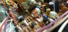
Okay, I pulled apart the whole phono board and every single transistor is a 2sa872. I have no idea what to make of that. That means there are no complimentary pairs? I don't understand enough about amp design to know whether this would actually work but it seems like it would not (based strictly on "intuition"... I really don't know a lot about amp design... I'm just a guy with a soldering iron and time )
)
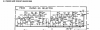
Here are the schematic and transistor list. Everything matches up, actually, EXCEPT THAT ALL THE TRANSISTORS ARE 2sa872 It's almost hard to believe that there isn't a value that was tweaked here or there!! Yet.... the only deviation is on the transistors.
I replaced Q401-404 already(which had previously had heat shrink on them? I assume maybe for some aid in heat dissipation?) with ksa992FTA before I started second guessing myself. My rationale was that either there was a hack job previously, or that rebuilding to the "factory schematic"... albeit with modern equivalents, would work. Now I don't know what to think.
)Here are the schematic and transistor list. Everything matches up, actually, EXCEPT THAT ALL THE TRANSISTORS ARE 2sa872
It's almost hard to believe that there isn't a value that was tweaked here or there!! Yet.... the only deviation is on the transistors.I replaced Q401-404 already(which had previously had heat shrink on them? I assume maybe for some aid in heat dissipation?) with ksa992FTA before I started second guessing myself. My rationale was that either there was a hack job previously, or that rebuilding to the "factory schematic"... albeit with modern equivalents, would work. Now I don't know what to think.
Attachments

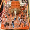
I see a C1775 to the lower left of the splined shaft. I dug through my 2330B rebuild pix and none are the version of board that you have but they're close. Only one of my pictures shows the one up front that is at a right angle to the other three and it's below. Remember that the service manual was likely done once and never changed although the boards changed. Even if they had different versions out, what was the one that was scanned that we have? Production changes happen. What ever you have in there though was working sometimes, right? If the polarity of transistors was wrong anywhere it would never work. At least you don't have the crappy A912's!
klamsoss
Be willing to fail and try again.
@rBuckner I am very grateful for your input on this. The photo from your work is a good point of reference! It looks like our two units have some differences. A few caps are different, but most notably there seems to be an additional transistor just to the right of the selector shaft. Interesting! and also par for the course on Marantz equipment... so many changes, so little matchup with the service manuals... 
AND
I needed to take a breather and look back at the section. I got frustrated, worked up, and my internal switch went from "normal" to "dummy" because of it.
They are NOT all 2sa872 transistors. 6 of the 8 are, and the remaining two are 2sc1775. I think there is probably a misprint on my board or in the parts list as far as labeling the Q numbers, too
*Please note the edit on KSA992FBTA. the KSA992FBU has a lower gain rating than the FBTA variant. in my application, the FBU variant was tried and produced notably lower output from the phono stage compared with what it should have been.*
So we have:
Q401-Q404 WERE 2sa872a in reality and on the parts list. I think these are labeled correctly on the board in terms of Q number. They have now been replaced with ksa992FBTA. This is a good replacement, yeah?????
Q405/407 are listed in the parts list as KSA912. I think that Q405 and 407 are mislabeled on my board.
The position labeled Q405 on my board is a ksc1775 --> I reason that this can be replaced with a 2sc1845 based on things I have seen in other threads.
The position labeled Q407 on my board is a ksa872a --> I reason this can be changed out to a ksa992FBTA based on that it's a suitable replacement for the other ksa872a transistors, and based on other threads.
The position labeled Q406 on my board is a ksc1775 --> 2sc1845
The position labeled Q408 on my board is a ksa872a --> ksa992FBTA
Do I have this right? These are suitable replacements?
my reasoning "based on other threads" comes mostly from your input here:
https://audiokarma.org/forums/index.php?threads/marantz-2330b-p400-phono-eq-board.746275/
And I believe I have seen these recommendations echoed in other threads by @Steven Tate on other marantz 2330B threads.
You guys have been goldmines for info on this and other projects (1060, 2325), and I'm deeply indebted to you (let me know if either of you are ever in the Cincinnati area... I'll buy you a beer or 6!!!)
AND
I needed to take a breather and look back at the section. I got frustrated, worked up, and my internal switch went from "normal" to "dummy" because of it.
They are NOT all 2sa872 transistors. 6 of the 8 are, and the remaining two are 2sc1775. I think there is probably a misprint on my board or in the parts list as far as labeling the Q numbers, too
*Please note the edit on KSA992FBTA. the KSA992FBU has a lower gain rating than the FBTA variant. in my application, the FBU variant was tried and produced notably lower output from the phono stage compared with what it should have been.*
So we have:
Q401-Q404 WERE 2sa872a in reality and on the parts list. I think these are labeled correctly on the board in terms of Q number. They have now been replaced with ksa992FBTA. This is a good replacement, yeah?????
Q405/407 are listed in the parts list as KSA912. I think that Q405 and 407 are mislabeled on my board.
The position labeled Q405 on my board is a ksc1775 --> I reason that this can be replaced with a 2sc1845 based on things I have seen in other threads.
The position labeled Q407 on my board is a ksa872a --> I reason this can be changed out to a ksa992FBTA based on that it's a suitable replacement for the other ksa872a transistors, and based on other threads.
The position labeled Q406 on my board is a ksc1775 --> 2sc1845
The position labeled Q408 on my board is a ksa872a --> ksa992FBTA
Do I have this right? These are suitable replacements?
my reasoning "based on other threads" comes mostly from your input here:
https://audiokarma.org/forums/index.php?threads/marantz-2330b-p400-phono-eq-board.746275/
And I believe I have seen these recommendations echoed in other threads by @Steven Tate on other marantz 2330B threads.
You guys have been goldmines for info on this and other projects (1060, 2325), and I'm deeply indebted to you (let me know if either of you are ever in the Cincinnati area... I'll buy you a beer or 6!!!)
Last edited:

Velox
Just a bug hunt, Ripley..
Well here's my 2330b that I worked on this year serial U071138, more phono board variations. I replaced all the electrolytics. Q401, 402, 403, 404 were 2SA872 and replaced with KSA992. Q407, 408 were replaced with KSA1013 (can't find my notes on what the originals were sorry). Had slight hum in phono before rebuild, hum gone after. The heat shrinked items at Q405, 406 I left alone after unwrapping one and finding two transistors and a resistor all tied together under the wrap. I apparently did not record what the transistors were under the heat shrink and after determining phono was working well I decided to leave well enough along there (not broke etc). If anyone knows what this board's variation at Q405, 406 with the dual transistors + resistor combo might be would appreciate that info. Receiver had shorted outputs, bad power supply etc all rebuilt and now sounds wonderful. Filter caps redone (stuffed with new) and could not initially identify an odd buzzing when powered on but soon found it coming from the power switch, replaced that and all's well. Thanks AK and posters here for the wonderful info available on this forum 

klamsoss
Be willing to fail and try again.
Note for all:
After a couple of test LPs, I went back in to swap the KSA992FBU transistors out for KSA992FBTA. Pay attention to the gain ratings for the replacements you use so that you can be sure your equipment will perform as it was designed to. The FBU variant has a gain rating of 300 while the FBTA variant has a gain rating of 430.
After a couple of test LPs, I went back in to swap the KSA992FBU transistors out for KSA992FBTA. Pay attention to the gain ratings for the replacements you use so that you can be sure your equipment will perform as it was designed to. The FBU variant has a gain rating of 300 while the FBTA variant has a gain rating of 430.

Can anyone make those pucks? I'd buy a bunch.I would use a clip lead to short from the capacitor lugs with the White wires to the chassis, then short from the capacitor lugs with the Red wires to the chassis. Notice that there are two capacitors to drain.
View attachment 1799686
To replace the NLA 'dual' filter capacitors with single ones, I do this:
View attachment 1799690
None of the electrolytic capacitors affect the tuning.
YMMV.
Tom
Tom
I’d be interested in a pair of those for my 2330b as well.Can anyone make those pucks? I'd buy a bunch.
View attachment 2868968
Still need some?I’d be interested in a pair of those for my 2330b as well.