
• The move to the new server is done. There are some software and database maintenance updates in process. This has us passing the hat around to help out. We appreciate any donations. Seriously, even a dollar helps. The payment page may be found here - https://www.audiokarma.org/support.html

A-60 protection circuit fault?

QSilver

Super Member
I got one an A-60 pretty cheap the other day, a bit ruffed up but salvagable. I think it has been a little wet at some stage as there is a bit of rust and some resistors were rusting on their legs. I've replaced the bad looking resistors and powered it on with DBT. All is well and the DBT goes dim, but the protection relay doesn't click in. Measuring the coil pins, I have +35VDC on both sides of the coil so the protection circuit isn't letting the relay come on.

I checked the DC offset and it was around 3mV or lower on both channels. I removed the output transistors to get better access to some of the resistors etc and tried agian without them in and still the protection circuit doesn't come on.

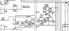
I took some readings around the circuit as best I can. I found the schematic but the X-Ray schematic is quite poor and I cant make out most of the writing so I'm following traces.

I took some measurements on Q706 which looks to operate the relay, and around D708 which is a Zener. Either side of R718, I have +35V, and then around 0.2V where I should have 13.5... or 15.5... I can't make it out so well on the schematic... I have 0V between the zener and Q706.

Is this working correctly and I need to looks somewhere else? I can't see a reason why protection let the relay engage but maybe I'm missing something?
 

Attachments

  • A-60 Protection.jpg
    A-60 Protection.jpg
    66.3 KB · Views: 7
Register to hide this ad
quick and dirty ...nothing connected to speaker terminals .briefly short q706 emitter and collector . if relay clicks in check q706 base is at 600mv or above ..if not we need to delve further .
 
quick and dirty ...nothing connected to speaker terminals .briefly short q706 emitter and collector . if relay clicks in check q706 base is at 600mv or above ..if not we need to delve further .

Relay clicked when I shorted E to C.

I checked the base of Q706... was strange... started out at 150mV then after I clicked the relay a few times it jumped to -1.8 to -2VDC... the strange thing is on the other side of the zener D708... the voltage is opposite... it is +1.8 to +2VDC.... I checked a few times with my black lead to ground...
 
I'm going to try and get back to this tomorrow and take some of those readings again.. is the Zener suspect or do we need to go deeper? I suspect deeper...
 
I checked C709. It tested ok but I replaced it anyway seen as it was out.

Q705 reads like this:
E 1.25~1.36VDC
C 0mV
B 650~760mV

Emitter and base readings move through that range.

I found a similar post here: http://audiokarma.org/forums/index.php?threads/pioneer-a-60-protection.604143/

So I lifted R716 which feeds D706 and D707 into the protection system and R713 + R714.

The protection system still did not release and I found that I had 0.8VDC on the Base of Q705.

Did a continuity test across D708 and it is not shorted.
 
if you was to take q705 out of the circuit then the relay should be clicking on if everything forwards of it is working properly
 
I pulled Q705 and after a few seconds the relay triggered. When powering off, the relay stays on for five or more seconds and then clicks back off. Powering back on, you can see the relay clicks back on again. The voltage between D708 and Q706 is now correct at 0.6VDC. What does this point to?

I checked the DC offset at the speaker terminals while the amp was out of protection and they are 1mV and 3.5mV DC.

Is Q705 leaking?
 
the voltages seem to suggest q705 is good . you could test it or replace it .
i need to study this some more to see how its all supposed to work .
 
Last edited:
the voltages seem to suggest q705 is good . you could test it or replace it .
i need to study this some more to see how its all supposed to work .

Q705 triggers Q706 so sometjing further down is triggerimg Q705 to hold Q706 in the protect stage?

Ill test Q705 shortly... What would be an okay sub?
 
did you check the bias ?
am thinking over-current might be getting triggered for some reason .
instructions are further down in the manual .
 
Ill check bias too... But afaik, ive disconnected the inputs from the amp to the protection circuit so over current shouldnt be detected atm...
 
Checked bias but ive removed the outputs so there is 0mV. I had also disconnected the over current sensor section.

I tested Q705 which tested ok, i then put back in curcuit and ut niw comes out if protection.....

Ill reconnect orotection to amp and see what happens...
 
mmmm.. maybe it had a dry joint or the heat from your iron temporarily fixed it .. have had that on the odd occasion with transistors .
 
Well i put the outputs back in. Relay clicked... But i have no idle current at all... Not even if i adjust the trimmers on both channels...
 
did you follow the manual ?
just looked again and it is simply over one emitter resistor .. dont know why they over complicated it .
 
Yes, TP1 and Pin 25 etc. I even tried checking across the output emitter resistors but there is 0mV even when I turn the trimmer up... I cud try passing a signal through... maybe it needs to warm up? 5mV isn't very much...

When powering up, you get a reading over TP1 and Pin 25 and as soon as the relay clicks, this drops to 0mV.
 
you could see how many mv at outputs bases ..should be +-600mv ish
drivers bases at +-1.2v .
as you follow back in circuit add 600mv from emitter to base .
 
So checking base voltage on the outputs Q525 and Q531, then Q530 and Q524, then Q528 and Q522?

So far, Q532 and Q526 have 3.5mV and Q525 and Q531 have 0.5 to 1mV...

With headphones, sound out of right channel is ok. Left channel is just... not biased at all...
 
yes .get base voltages for those mentioned .
p.s is the unit running off full mains voltage ? as in no dbt or variac etc
 
Back
Top Bottom