• The move to the new server is done. There are some software and database maintenance updates in process. This has us passing the hat around to help out. We appreciate any donations. Seriously, even a dollar helps. The payment page may be found here - https://www.audiokarma.org/support.html

A-60 protection circuit fault?

Base readings

Q525: 3mV
Q531: 3mV both move between 0mV and 3mV

Q532: 476mV
Q526: 478mV

Q523: 26mV
Q529: 3mV

Q527: 581mV
Q521: 598mV

Q528: 1.6V
Q524: 1V

Q530: 1V
Q522: 470mV

As I was taking the readings the amp went back into protection so I suspect that Q705 might be failing?

I've got it on a DBT. 60W bulb. the bulb goes very dim. I was running it on a 100W when reassembled for the first time but dropping to 60W just for safety.
 
I'm starting to see a pattern and a thought just came to mind.... could a problem with the 12k resistors cause something like this? I seem to remember thinking some 12k resistors looked suspect but I left them as I had no 12k to replace them with....

R593, R569, R579, R595 etc?
 
i think its simply a case of low voltages due to the dbt .. try a higher wattage and see if those bases get more near the ball park ..
transistors need around 600mv on the bases to start switching on .
and yes those resistors would affect the biasing .
 
I put it through on a bigger bulbs and then two in parallel but it didn't seem to make much of a change to the voltages. they still stayed around 470mV. However, I may have misread Q522 as that now reads 1.6V as I think it should.

There might be an issue with the 12k resistors or something in that area as the voltage is half of the other channel across one of them. I have 13k resistors but no 12k as of yet...
 
1.8 would be more like it . it all depends on the turn on voltages of the transistors .. some earlier ones were a bit lower .
 
1.8 would be more like it . it all depends on the turn on voltages of the transistors .. some earlier ones were a bit lower .

Yes sorry, I meant that at least now, it matches it's counter part. I did notice that I did not get a good reading until i pressed hard into the solder so the surface of the solder joints must have some oxide i need to pierce to get a good reading...

Perhaps on that channel that souds ok, adjusting the trimmer would lift them to 1.8 etc? But the other channel is still very much off.
 
you are looking in the right place . let me get this right ..the voltage drops are higher in the bad channel on the 12k resistors ? if so check drop over each resistor . all 4 being bad would make me wonder .
if its just one or maybe 2 you nailed it .
 
Yes, I think the voltage drops are higher in the bad channel compared to the good one. But I'll need to check and confirm tomorrow. I should probably order some 12k resistors....
 
if its all of them dropping same voltage it will be some other problem . 4 going bad and same way i dont buy right now ... but i keep an open mind .
 
I went through and checked the 12k resistors for both sides and they are all working. They drop the voltage from 60V, down to 31.5 and then down to 1.4 on each side (+/-) so they aren't the problem.

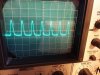
I took out the wave generator and scope and did some quick probing, the signal is healthy when it comes back from the volume control at connector F, but when it re appears at connector B, it has the distortion - most of the negative side of the curve is missing... this would seem to suggest there is a problem in the control board or feedback loop? At least, I think that it is a feedback loop...?

Also, the protection circuit has stopped working completely again, so for the moment, I've pulled Q705 again. just to confirm the relay driver is working and it is.
 
i see connector f at vol outs but not finding connector b ..where is it situated ?
on another note i seem to remember you disconnected all triggering for protect circuit ? if so protect circuit is playing up or power supply is .
maybe check all power supply voltages next for good measure .. this is usually the best place to start as it happens .
 
Connector B goes from the tone controls back into the amplifier board - just above connector F.

I had fully reconnected the protection circuit again. Only thing I've removed again now is Q705 but I'm not measuring anything coming through on the sensors. R713, R714 both have 0.3mV on them.

I've checked power supplies - they seem good.
69V: 68.4+, 68.4-,
40.5V: 40.4+, 40.4-,
Regulated 20V: 19.7+, 19.7-
20V regulated for LED driver etc: 19.5V
 
I think B will have distortion as it is being fed from the feedback loop coming back from the output of the amplifier... Signal come sin clean on one side of Q501 and it's distorted on the other side. Voltages on Q501,Q503 and Q505 match up with their counterparts on the channel with no distortion... so my thought is that it must be being introduced further in and then the feedback loop masks it...? I took a output of the scope and it looks like the negative side of the sinewave is very underbiased and not coming on while the positive half seems... pinched?

I also tried a small square wave and with this, both sides were symmetrical with a curved rise and sharp fall...
 

Attachments

  • 20160828_151722.jpg
    20160828_151722.jpg
    85.4 KB · Views: 3
Solved the distortion issue! I checked Q519 and compared it to Q520 on the other channel and the collector voltage was very low. 0.5V vs 28V.

I took out Q519 and tested it and found that at the start it had no gain and then very slowly started to rise. So I replaced Q519 with a KSC2383YTA and the channel is working again.

I did check resistors too and all is correct so far...

I also found a dry joint on the STV-4H on the right channel.

I ended up replacing Q519, Q520, Q509 and Q510. As thier gain was 50 or under. Gain matched pairs of KSC2383YTA and KSA1031YTA as best I could (HFE 200 ish)

Still need to sort out protection circuit and find out if that has also cured the idle current... moving in the right direction though!
 
might be just as easy to change the other transistors in protect circuit and the capacitors . plus check resistor values .
 
Yes, changed out Q705, Q704 and Q703 in the protection circuit for a KSA992FBU and two KSC1845's and now its working properly.

Idle current is now there and can be adjusted with the trimmers so for now I have it at 3.5mV and the amp warmed up very slightly so I think all is good now. There are a few little things I need to finish, just recapped the phono pre amp board and dis assembled and rubbed down sections of the chassis that have some rust spots on. Will respray them tomorrow.... the lid looks a little rough too.... I might strip it too.

I'll order some 12k resistors to replace the flaky ones and any others that dont look right along with some diodes that are looking a little corroded too...
 
Yes, its the most complex I've worked on I think... with the dynamic power supply but I think all of that is behaving but we'll see.... thanks for all your help so far!
 
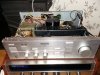
Resprayed parts of the chassis today, and then reassembled after finishing changing some hard to get to capacitors and applying new thermal paste to the LED driver regulator. Put it all back together minus the top cover which still requires work and gave it a work out on my PD-91. sounding very good! Plenty of power and a really clear easy-to-listen-to sound. Just need to order those 12k resistors, a few more caps and regrease the power transistors and that could be it!

Apologies for the poor picture....
 

Attachments

  • 20160829_212714.jpg
    20160829_212714.jpg
    101.9 KB · Views: 5
Back
Top Bottom