• The move to the new server is done. There are some software and database maintenance updates in process. This has us passing the hat around to help out. We appreciate any donations. Seriously, even a dollar helps. The payment page may be found here - https://www.audiokarma.org/support.html

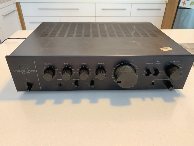
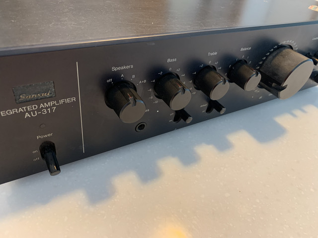
a newbie, a sansui (AU-317) and a community :)

esteboune

BleuBlancRouge
Hello everyone,

Right now everyone is talking about the Coronavirus, but I contracted another virus:
the Vintage Virus!

Long story short, I sold all my modern gear (except speakers) and I really, really enjoy learning about 70s receivers and amplifiers.

I have now the following equipment:
Yamaha CA-1000 and CR-1020
Accuphase C200 + P300
Luxman 5L15
Sansui AU-317

I bought the last one at a reasonable price and I want to give it (him? her?) a second life!
It is working correctly, maybe a slight imbalance between the 2 channels.

This forum is such a fantastic source of information and lesson learnt.
thanks a lot to @Karl vd Berg for your great past thread, you inspired me!
https://audiokarma.org/forums/index.php?threads/sansui-au-317-vs-au-317-mk-ii.490174/

This will be my first rodeo!
I am not too bad with a soldering iron, and I think I can understand schematics.
However, I am taking all good advice !

My plan:
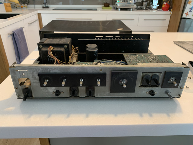
  1. cleaning all internal and external parts (including the glue)
  2. changing all the fuse resistors
  3. changing electrolytic capacitors
  4. Certainly changing some Diodes, transistors and VRs
  5. DC Offset
  6. Bias adjustment
  7. Optional, repainting the case?
Pictures will follow soon!

cheers
Etienne
 
Register to hide this ad
Welcome to the endless money pit. Lol. These Sansui receivers are great and with some TLC will work for years to come. Looks like you have a great plan, don't go too crazy replacing things, not all transistors are bad & there is no need to replace them. Fusible resistors definitely and electrolytic capacitors for sure. I would leave that modification in there. Quite often Sansui made updates to circuit boards mid-production and did not update service manuals or schematics. I've had that with almost every Sansui I've worked on. They've even completely changed to new boards in some units. Makes it a bit difficult to service but leave any modifications in there. Same goes for components, they sometimes changed values of resistors and capacitors mid-production. Replace with what is in the amp, not what the schematic says. Good luck.
 
Sorry, typo. But all the same to repair other than FM alignment. The amp and preamp sections are what needs the most work always.
 
Welcome to the endless money pit. Lol. These Sansui receivers are great and with some TLC will work for years to come. Looks like you have a great plan, don't go too crazy replacing things, not all transistors are bad & there is no need to replace them. Fusible resistors definitely and electrolytic capacitors for sure. I would leave that modification in there. Quite often Sansui made updates to circuit boards mid-production and did not update service manuals or schematics. I've had that with almost every Sansui I've worked on. They've even completely changed to new boards in some units. Makes it a bit difficult to service but leave any modifications in there. Same goes for components, they sometimes changed values of resistors and capacitors mid-production. Replace with what is in the amp, not what the schematic says. Good luck.
Thanks a lot for your message.

i will try to make at as easy as possible!

i am now working on the schematics:


One important question:
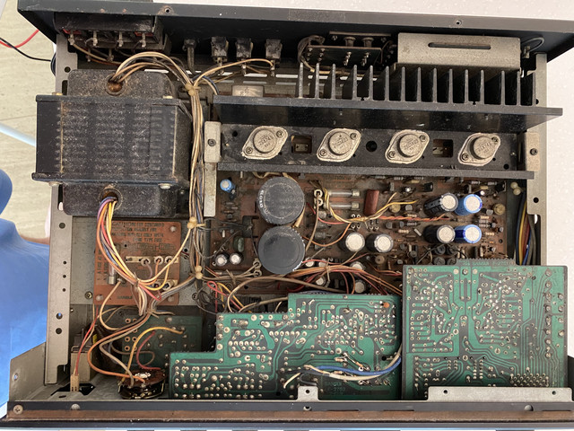
I will start working on the Power Amp Board F-2754, I am wondering if I should completely remove it from the chassis or if I should try to work on it with all the wires still connected.

I am actually worried about making mistakes reconnecting all the wires!

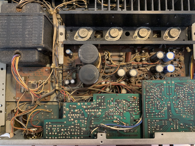
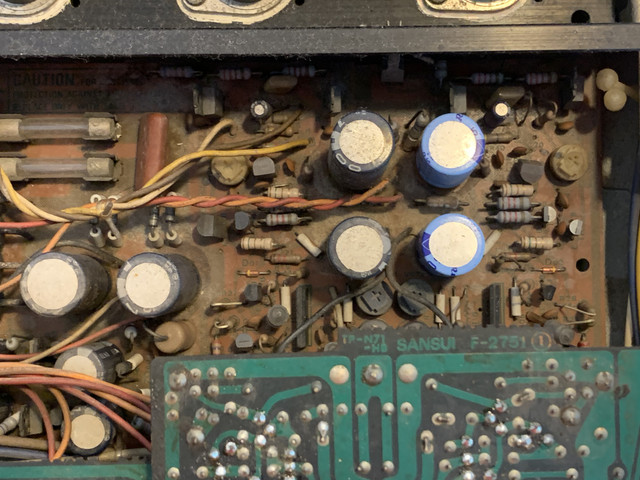
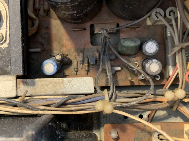
On the other hand, the board is so dirty, it will greatly benefit from a deep cleaning.
 
Take photographs and document the order you do things in. Label bags for screws etc. I would remove the board, much easier to work on. Sansui boards are well labeled but there have been mistakes at times. Get a large bottle of isopropyl alcohol, you'll certainly need it with all that crud. I would start with an air compressor & blow out as much as possible. I can see one of the large caps is swollen, possibly been stressed so I would not reconnect the power supply to the rest of the amp, test the voltages first. If it checks out then move onto the next board. I would not reconnect power until checking output and drive transistors, diodes etc on all the boards looking for shorts. A semiconductor checker is a very handy tool. I'd highly recommend a Peak Atlas DCA55. It will really help you. Lots of help on this forum so always ask.
 
I will remove the Power Amp Board F-2754 this weekend.
today, I worked on my shopping list!

I focus first on the Power supply, regulators, and protection sections


Mouser project:

https://my.mouser.com/ProjectManage...jectGUID=6cb715b6-2649-446b-9c37-56a997d922dd

I understood that for the PSU it is possible and advisable to increase a little bit the capacitance.
I mainly followed @Karl vd Berg 2017 list, and I played around a little bit in order to get available items.

As you can see it is mainly Panasonic FR.

regarding the C602 and C615, i noticed that no one changed them, what is the reason?

Do you recommend me to change the diodes as well?
  • D602~D605
  • D601, D606~D609, D610
  • ZD601, ZD602
 
Last edited:
That's a good list. I know it is quite common for people to increase the value of power supply capacitors thinking it will help the amp but it actually has the opposite effect. The rule is generally to increase the voltage but not the capacitance. Higher capacitance puts a strain on the power supply at start up and can result in premature failure of diodes and regulators. You will be drawing higher current to charge the capacitors unless you modify the circuit and install a slow startup feature. You could go up a small amount to 12000uf but the jump to 15000uf is a 50% increase, I would not do that. The important thing with these 2 caps is the physical size, they are big for a reason, do not put in physically smaller capacitors that's okay elsewhere but not the main filter capacitors. Diodes are up to you depending on if they have failed or not. I would generally replace the zeners but not the rectifier diodes unless there is visible damage from heat or corrosion. Watch out for corrosion on other components like resistors from the terrible glue they used on the capacitors. I would check all the resistors to make sure they are within tolerance. There is no need to change C602 and C615, these will last forever. I usually do not change greencap or ceramic capacitors unless they have obviously failed, these are super reliable and long life. The diode to change is D01, D02 VD1212 on the Equalizer board, these fail.
 
The diode to change is D01, D02 VD1212 on the Equalizer board, these fail.

Good to know! Would you be able to recommend a replacement? It seems the original diodes (VD1212) are no longer available.

Apologies for the hijack, OP (I’m in the middle of restoring my own AU-317 and hopefully this question helps you as well!)
 
That's a good list. I know it is quite common for people to increase the value of power supply capacitors thinking it will help the amp but it actually has the opposite effect. The rule is generally to increase the voltage but not the capacitance. Higher capacitance puts a strain on the power supply at start up and can result in premature failure of diodes and regulators. You will be drawing higher current to charge the capacitors unless you modify the circuit and install a slow startup feature. You could go up a small amount to 12000uf but the jump to 15000uf is a 50% increase, I would not do that. The important thing with these 2 caps is the physical size, they are big for a reason, do not put in physically smaller capacitors that's okay elsewhere but not the main filter capacitors. Diodes are up to you depending on if they have failed or not. I would generally replace the zeners but not the rectifier diodes unless there is visible damage from heat or corrosion. Watch out for corrosion on other components like resistors from the terrible glue they used on the capacitors. I would check all the resistors to make sure they are within tolerance. There is no need to change C602 and C615, these will last forever. I usually do not change greencap or ceramic capacitors unless they have obviously failed, these are super reliable and long life. The diode to change is D01, D02 VD1212 on the Equalizer board, these fail.
Thanks a lot @Sglaw461 .
Very good advice
i will correct my selected replacement parts accordingly.
 
Good to know! Would you be able to recommend a replacement? It seems the original diodes (VD1212) are no longer available.

Apologies for the hijack, OP (I’m in the middle of restoring my own AU-317 and hopefully this question helps you as well!)
Replace the VD1212's with a pair of 1N4148's in series

If you need to replace D1 and D2 which are 1S2473D's - these also can be replaced by 1N4148's
===========
Also if replacing all Zener's - ZD603~ZD606 - EQA01-18R --- replacements are: BZX55C18 or 1N5248B 5% types // BZX55B18 or BZX79B18 2% types
 
I noticed that my AU-317 is a revision B:


I am assuming the Schematics will be a little different.

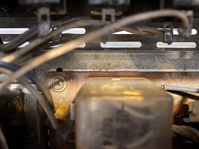
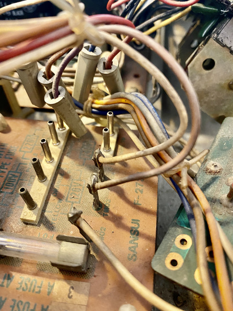
I started the process of removing all the boards.


so dirty !

time to desolder the wires...


I will take a lot of pictures and I will try to rely on the schematics, but still, I am a bit afraid of not being able to re-wire everything correctly in the future.

Any great advice?

Are you labeling all the wires?

thank you so much, everyone, for your support
 
Hi,

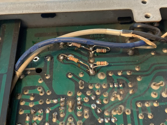
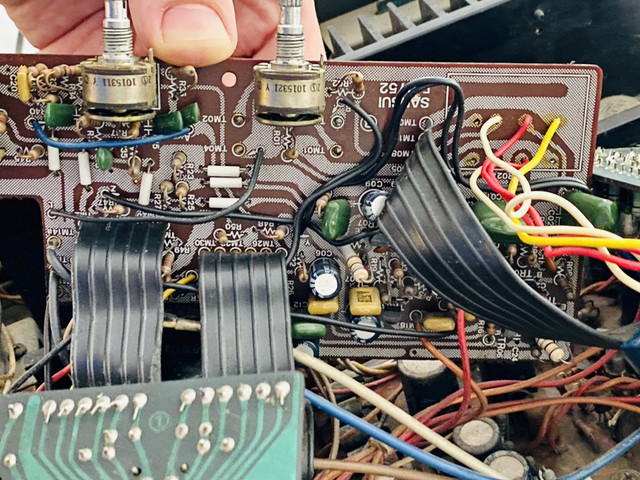
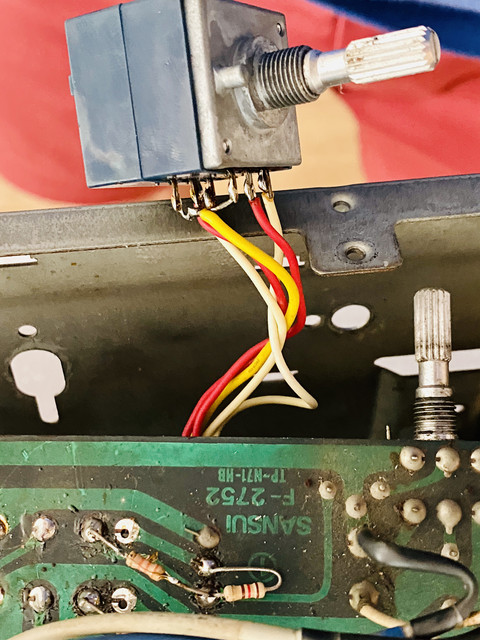
re the resistors mounted on the rear side of the tone control board, this is not a factory mod, there looks like there has been other work done on that board as there are quite a few solder joints that look suspect, and the insulation on many of the wires going to the board have been touched by a soldering iron. now that the component side of the tone control board cab be seen in the pot above, it is as I originally suspected. The volume pot has been replaced and it doesn’t have a loudness tap, hence the added resistors on the back of the board (possibly trying to mimic a loudness tap function). Is there any part number or markings on the volume pot that is fitted?

Cheers

John
 
Gents,

quick one!

I am looking for a replacement for C601, 50V, 47uF. It seems there are 2 options available on Mouser:


667-EEU-FR1H470B
50V 47uF

667-EEU-FR1J470B
63V 47uF

The 50V version has a lower ESR and higher ripple current.


Which one is the most suitable?!

thanks in advance
 
Back
Top Bottom