• The move to the new server is done. There are some software and database maintenance updates in process. This has us passing the hat around to help out. We appreciate any donations. Seriously, even a dollar helps. The payment page may be found here - https://www.audiokarma.org/support.html

a newbie, a sansui (AU-317) and a community :)

an update for tonight (yes soon time to go to bed for me!)

I removed most of the components I decided to change (the 2x10000uf gave me a hard time)
I cleaned the board, I struggle with the infamous glue...
and
I ordered all the parts required to rebuild my 317:

For the caps, I used a mix of Nichicon UPW for the power board, Silmic II for the Signal path, Muse ES for the BiPolar...
Hope I did not make any mistake!

upload_2020-9-22_21-57-21.png

Do let me know if anyone needs the XLS file.

Mouser project:
https://www.mouser.com/ProjectManager/ProjectDetail.aspx?AccessID=bfa3b69a21

Next steps, while waiting for the parts:
  1. finish cleaning the boards and chassis
  2. decide what to do with the volume pot (non Orginal and mounted weirdly)

I am learning a lot, and love it.
Thank you so much for your kind guidance!
 
You can use higher voltage ratings for capacitors' replacements.
If the originals are the minimum 6.3V or 10V, you can choose 25V or 35V versions, that give extra margins, higher ripple current number (in general), and possible longer working life.
 
Last edited:
You can use higher voltage ratings for capacitors' replacements.
If the originals are the minimum 6.3V or 10V, you can choose 25V or 35V versions, that give extra margins, higher ripple current number (in general), and possible longer working life.
thanks Karl for the advice.
 
Can someone please confirm that the on the 4 pins (50V, 10,000uF) only 2 pins are actually connected.
It seems the other one are not connecting to any trace on the PCB
 
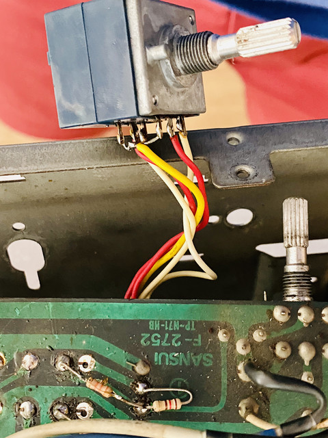
while waiting for the parts to make the 9,670 mi between Dallas to Kuala Lumpur, I would like to tackle the volume Pot issue.

As rightfully mentioned by John (@skippy124), the volume pot is not the original one, and its installation seems a bit awkward.

Some pictures:


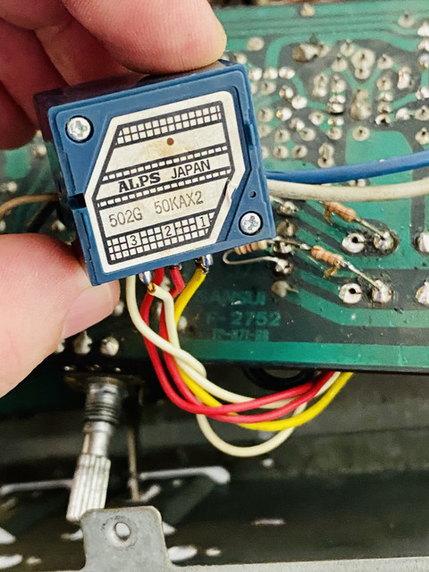
It is an Alps, but not the original one I guess.

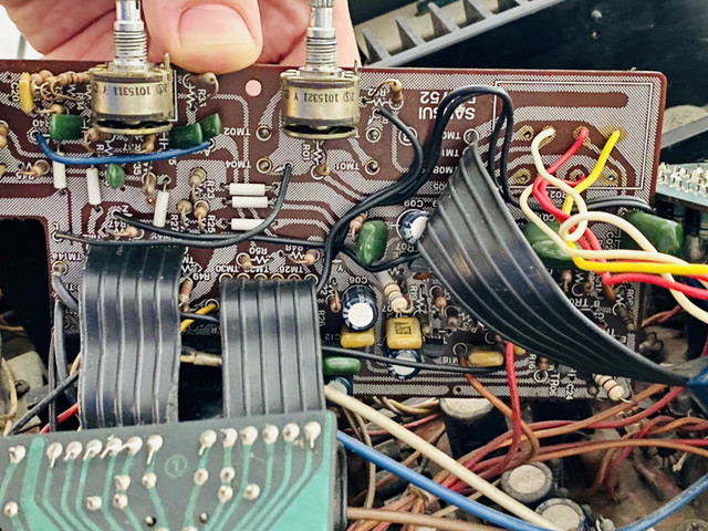
It is not directly soldered on the F-2752 board, but it is connected to 5 wires.

Finally, 4 resistors have been installed on the back of the board as follows:


i am afraid i do not understand the logic here!

what would you do?!

 
i am afraid i do not understand the logic here!

what would you do?!
The replacement Alps pot could be the wrong value, it should be 250KΩ according to the SM, or 150KΩ according to the schematic, I don't know what the correct value is. It also does not appear to have 'Loudness Taps' as the original would have had. The additional resistors may be an attempt to correct for this omission.
 
Last edited:
while waiting for the parts to make the 9,670 mi between Dallas to Kuala Lumpur, I would like to tackle the volume Pot issue.

As rightfully mentioned by John (@skippy124), the volume pot is not the original one, and its installation seems a bit awkward.

Some pictures:


It is an Alps, but not the original one I guess.

It is not directly soldered on the F-2752 board, but it is connected to 5 wires.

Finally, 4 resistors have been installed on the back of the board as follows:


i am afraid i do not understand the logic here!

what would you do?!

Looks like the resistors have been added in an attempt to have some form of loudness function from a standard (no loudness tap) volume pot that has been fitted to your 317. I’ll bet that there are some wires missing between the tone control board and the equaliser board (the loudness switch and associated components are mounted on the equaliser board).

The consensus is that the correct value of the original pot is 150K, and this value seems to be particularly hard to find. There are “ALPS” 100k or 250k pots (similar to the one that has been fitted to your 317) available on the ‘Bay, and 100k would most likely be the best value to go for rather than 250k.

Do a search with keywords of “alps 100k volume loudness” and you should get dozen or so results (China supplier so do a worldwide search). I have purchased one of these types of pots previously and it looked ok and tracking between sides was pretty good.

You will need to restore the loudness connections as per the schematic if you replace the pot that is fitted, and remove the resistors that have been added as well as checking that no PCB track modifications have been done around these resistors.

Cheers

John
 
Update, not a good one I am afraid...

I finished putting back all the completed boards in the chassis, soldered all the wires at the right place.

I tested the amp using the Dim Bulb Tester:


there is apparently a short!

I noticed that if I remove the 2 brown wires, the relay engage and the dim bulb tester is OK.

I then decided to test the Transformer...

Of course, i carefully checked the transformer connection:

It is set up for 240V as follow.


Blue, orange, and yellow are connected as per the instruction for 240V
Purple and Red are connected on the Spare TM

White Wire on TM03
Brown Wire on TM04'
(oppositive on the schematics, weird)

There is another white wire connected to the N of the power plug at the back of the amplifier.

Now the interesting part

when I am testing the AC voltage on the Brow and Gray wires at the output of the transformer this is what is get:

2 brown wires = 31.93 VAC

1st gray wire = 23.60 VAC
2nd gray wire = 7.30 VAC

FYI the black connection of the multimeter is on the chassis (connected to GND).

Does this make any sense?

is the transfo malfunctioning?

thanks for your help
 
Hold on!

i just realized while posting the message that the measure for the ouput transformer is not between GND and the wire, but between the 2 wires of the same color?!

Am i correct?

if so Brow: 63VAC
Gray 22VAC
 
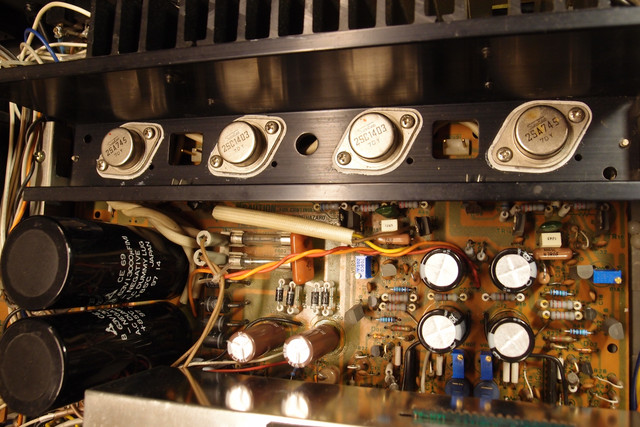
Just to be sure: are you following the pictured 1-2-3-4 marked arrangement above back to the board / on heatsink?
Because it should be 2SA745 - 2SC1403 - 2SC1403 - 2SA745.
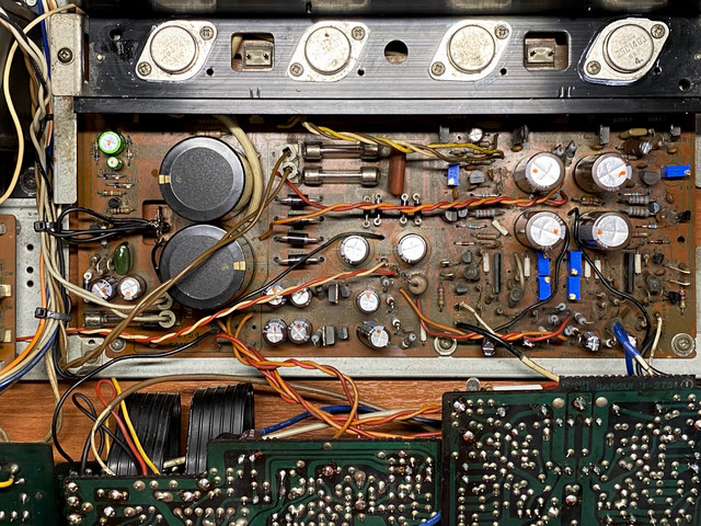
wow...

i did not see that coming Karl!

you are completely right...

i messed it up:
2SA745 - 2SC1403 2SA745 - 2SC1403


i will fix that on Monday, hopefully, i did not damage anything...

i feel bad!

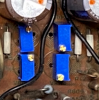
Moreover, i noticed that the group of 4 VR on my board does not look like yours:

upload_2020-10-3_9-7-32.png
 
above, my job
@Karl vd Berg 's job:

OLYMPUS-DIGITAL-CAMERA.jpg


did I install the Top 2 Vrs on the wrong side

I will visually check tomorrow at the office!
 
Back
Top Bottom