• The move to the new server is done. There are some software and database maintenance updates in process. This has us passing the hat around to help out. We appreciate any donations. Seriously, even a dollar helps. The payment page may be found here - https://www.audiokarma.org/support.html

Accuphase E-202 blown power supply

Tala Mink

Active Member
I started working on an Accuphase e-202 for a friend, they weren't sure what was wrong with it as it had been sitting for almost a year since it stopped working.

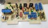
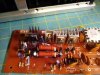
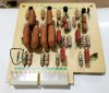
I was going to power it up on a dim bulb to see what was wrong with it, but opened up the amp first to see if anything was visibly wrong and saw an extremely leaky filter capacitor and a blown power supply so i decided not to power the unit up.
as you can see there are multiple bad resistors but the weird thing is that with a basic in circuit diode check on my multimeter, all the transistors and diodes in the power supply test normal.
I have never seen something fail so badly without a bad transistor so I wanted to know if a cold solder joint could be the cause as this board gets tons of heat or if I should start pulling transistors and checking them with a tester.
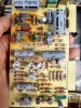
IMG_20221105_112716239_HDR.jpg IMG_20221105_105732551.jpg so far I'm planning on replacing the filter caps along with the resistors and gray elnas in the power supply. I checked the output transistors and the rectifier diodes for the main amp and they test good. right now I want this thing to safely power on then I can see/hear if there are any other problems.
 

Attachments

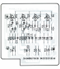
  • accuphase power supply.PNG
    accuphase power supply.PNG
    585.6 KB · Views: 69
Register to hide this ad
It appears that R6 has blistered, and possibly R12. The pass regulators run very hot in this and can benefit from added heat sink to help dissipate more BTUs.

Be aware that there are "early" and "late" versions of this unit, with the break being somewhere around 1977.
 
It appears that R6 has blistered, and possibly R12
Yes, R6, R12, R29, R33, and R35 Have either cracked or blistered.
R27 and R28 look like overcooked hot dogs and may have failed due to heat alone so I'm going to replace them with 2watt instead of the original 1 watt.
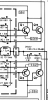
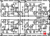
I'm not super knowledgeable in circuit design but I would assume the pass regulators are Q9 and Q10, I do have some larger transistor heatsinks but to add them I would have to mount the components above Q10 and Q9 on the back of the pcb which I will consider when I have this thing working.
 
I started working on an Accuphase e-202 for a friend, they weren't sure what was wrong with it as it had been sitting for almost a year since it stopped working.

I was going to power it up on a dim bulb to see what was wrong with it, but opened up the amp first to see if anything was visibly wrong and saw an extremely leaky filter capacitor and a blown power supply so i decided not to power the unit up.
as you can see there are multiple bad resistors but the weird thing is that with a basic in circuit diode check on my multimeter, all the transistors and diodes in the power supply test normal.
I have never seen something fail so badly without a bad transistor so I wanted to know if a cold solder joint could be the cause as this board gets tons of heat or if I should start pulling transistors and checking them with a tester.
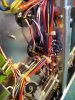
View attachment 2708274 View attachment 2708275 so far I'm planning on replacing the filter caps along with the resistors and gray elnas in the power supply. I checked the output transistors and the rectifier diodes for the main amp and they test good. right now I want this thing to safely power on then I can see/hear if there are any other problems.
Once you remove that leaky cap test it to see if it shorted out.
 
Once you remove that leaky cap test it to see if it shorted out.
I did test the leaky cap and it read as 600ohms which while being really bad is about what I suspected as a shorted cap would either have blown the fuse or an amplifier channel.

I took out the old thin silver looking heat sinks and use new ones (https://audiokarma.org/forums/index.php?threads/accuphase-e-202-restoration.985700/)
IMG_20221107_180340792.jpg I'm going to replace the heatsinks with something from this board
also I wasn't aware of that thread and it has a lot of useful information, if it was my amplifier I would do a full recap (not because it needs one but because I recap every vintage amp I own) but my friend just wants it to work, nothing else.

I would consider making an offer for it but I have quite a few projects going on right now.
 
Update.
I replaced the bad resistors in the power supply along with the filter caps and the 3 caps in each amp board, now the right channel has problems.

powered it up with just the power supply in - relay clicks
powered up with both amp boards in - bulb glows and relay does not click
powered up with only left channel in - dim bulb and relay clicks
switch left channel board to right channel - bulb glows and relay does not click

I removed the output transistors and tested them with a transistor tester and they test good

I removed both amp boards, powered up the amplifier and checked the voltages on the pins and here are the discrepancies.
Good - 35v 44 -7 -16 0.7 -1.1
pin - 2 3 4 5 9 10
Bad - 13v 8.5 -50 -45 3.5 -39

I haven't experienced this problem before and my guess is that some of the output transistors are bad but like I said, they test fine.
 

Attachments

  • da dafgaggaagagragrga.PNG
    da dafgaggaagagragrga.PNG
    245.9 KB · Views: 10
Last edited:
depends how you are checking them, + all transistors on that board need checking

I used a multimeter diode check in circuit, and an atlas dca55 out of circuit. NPN's test as NPN's and PNP's test as PNP's.
like I said I swapped the board I know is working to the right channel (still only one amp board in) and the amp draws too much current.

I did forget to write down the test characteristics of the output transistors and ill do that later.
 
One 2SA679 has a gain of 63 the other has a gain of 25
2SA1079's gains are 47 and 32
 
Last edited:
Swap the output transistors between the good and bad sides.

I just swapped the output transistors in the left channel to the right and the relay clicked on.

I'm going to replace all 8 output transistors. I haven't done any research yet but does anybody have any recommendations on replacements.
 
I forgot to update this thread because I had a few other projects at the time.

I ended up using MJ21195/96 for the outputs, the amp sounded great after bias and offset adjustment, I didn't envision seeing one again so I bought it and ended up paying way more than I thought I ever would for an amplifier but I'm pretty cheap so its not a very high bar.

I ordered some 1N4148 diodes for my 517 and dumbly decided to replace the diodes in the accuphase without crosschecking with the schematic, I replaced all the standard diodes on the power supply board but then i replaced the zener in the filter amp mistaking it for a normal silicone, now i have no idea where the Zener went and cant find a datasheet for the original ( XZ-122 ).

The only place I can find referencing XZ-122 NTE which gives the replacement as a 1watt 12v, I cant see how this is right as the schematic (for the older version, also the one in sanjib's restoration thread) shows -40v and has no zener.
I haven't put the board back in and powered it on so I have no idea if this will really have any impact on the amplifier, the voltage runs to the collectors of the pnp's on the filter amp (high, low, and subsonic).

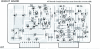
I added the Zener symbol to the schematic.000400.png 714-0004.PNG
 
The SM on Electrotanya shows a 'Revised' E-202 schematic that shows an XZ-122 Zener - BUT - it's D5 in the Eq. Amp (711-0002-10), where a 12V Zener does appear to make sense.

The same manual shows no diodes (or Zeners) at all in the Filter Amp ?
 
According to the schematic and parts list the D1 is the XZ-122, but in my unit, it is jumped with a wire.

Filter Amp_After_marked D1.jpg
 
According to the schematic and parts list the D1 is the XZ-122, but in my unit, it is jumped with a wire.
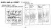
The manual version I'm looking at (from Electrotanya), is showing a D1 Zener on the Filter Amp PCB layout diagram, but not listing it in the parts list (that's why I didn't recognise it as an 'XZ-122'), and not showing it in the overall "E-202 Revised Schematic Diagram" either...

Filter Amp PCB Layout & Parts List.jpg
Revised Schematic.jpg

Looking again now - there are multiple files for the E-202 on Electrotanya... which probably explains the / my confusion. I guess it comes down to the OP's actual version of the amp...
 
Mine is the later version with XZ-122, I'm just not sure what the correct voltage replacement is for the Zener is.

NTE says a12v 1w Zener is a replacement but they are known to be wrong about replacements for lesser known parts.

I'm not too knowledgeable about circuits but I assume the Zener was put there to regulate the -40v so the replacement might be a 39v 1 or 1/2 watt.
 
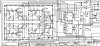
One of the other schematics / service manuals on the Electrotanya site does show the D1 (XZ-122) Zener on the schematic - as follows. From the schematic indicated voltages either side of that Zener (-28V & -40V) it would seem perfectly reasonable that it's a 12V Zener.

If you assume in the worst case, that the full 37.2mA current shown on that trace is passed by the Zener (the schematic actually suggests it'll be lower than that), then the Zener would be dissipating ca. 0.45W, so a 1W rated Zener also seems quite reasonable.

With no other information, I'd go with a 12V @ 1W.

D1 Zener Schematic.jpg
 
okay that makes sense.
I didn't know there as another manual that shows the voltage after the zener.
thanks for the explanation Goldie99.
 
Back
Top Bottom