• The move to the new server is done. There are some software and database maintenance updates in process. This has us passing the hat around to help out. We appreciate any donations. Seriously, even a dollar helps. The payment page may be found here - https://www.audiokarma.org/support.html

across the bench: an electronic menagerie of diagnostic oddities plus photos and design analysis

aea 620 - 17.jpg
ribbon cable on this side of the rear board feeds the meters and selector switch (sensitivity). cable on the other side has fewer pins and send input signal to the volume pot, lots to noise potential not to mention the pot itself is slightly unbalanced (L vs R resistance sweep).
 
aea 620 - 18.jpg
and now the bias/offset headache for the lower side of each channel. this view is when looking through the vents on the bottom of the amp chassis.

aea 620 - 19.jpg
small adjustment screwdriver typically included with various electronic device purchases

aea 620 - 20.jpg
35mm of reach which appears to be just enough to adjust the lower pots. a case of 100 of these probably costs around 1 usd to manufacture or something.
 
aea 620 - 21.jpg
fairly easy to remove the face plate

aea 620 - 22.jpg
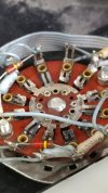
closer look at the meter selector and the condition of the completely exposed electrical contacts
 
aea 620 - 25.jpg
testing functionality after the initial repairs and dialing in the meters with measurements and calculations

aea 620 - 41.jpeg
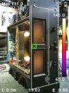
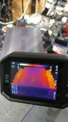
mugshot for the thermals

aea 620 - 42.jpeg
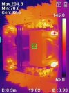
low temp scan range will be adjusted in upcoming posts, 85f instead of 65f
 
aea 620 - 43.jpeg
backlight bulbs seems to be stealing the thermal show

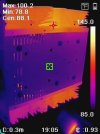
aea 620 - 44.jpeg
adjusted to 85f scale, i should consider multiple thermal color schemes for a better perception of thermal conduction

aea 620 - 45.jpeg
outputs warmed up after the low wattage meter calibration, bottom panel view
 
aea 620 - 26.jpg
with a successful signal/music test, now its time to update the right channel before another cap related meltdown occurs. rear panel board needs some new caps as well.
 
aea 620 - 28.jpg
rear board all set, reconnecting the pair of 10 pin ribbon cables will be the primary headache. should seriously consider a conversion to a 10 pin header and a solderable adapter for the cable. converting the speaker terminal interior connections to fast-ons would also help.
 
aea 620 - 29.jpg
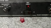
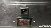
closer look at the reset button and LED assembly

aea 620 - 30.jpg
light emitting diode soldered to a round casing adapter, similar to a 22 caliber short only with an electrode as a primer. red plastic button is a simple extraction, slight locking barb that is easy to pull out.

aea 620 - 31.jpg
might be able to hit the hidden switch contacts with some spray to improve button electrical response
 
aea 620 - 32.jpg
light "on", amp is active and ready to make some noise

aea 620 - 33.jpg
light "off", amp is in mute or some type of standby/protection mode. mains wattage shows some interesting numbers.
 
aea 620 - 34.jpg
amp "on" and active at idle, final numbers (upcoming posts) after testing system max wattage are sitting around 55w. which also includes 0.5w x2 LED backlight bulb consumption vs 7w original space heaters.

aea 620 - 35.jpg
after pressing the reset button, power factor about the same but current consumption definitely decreased. no audio output possible in this mode.

even after the high output measurements the idle at mute/standby/protection stays around 26w and did not drift higher.
 
aea 620 - 37.jpg
photo notes about pot dial position, right channel: bias/phase on the left and dc offset on the right

aea 620 - 38.jpg
left channel pots, both photos are the upper pots since the lower pots are difficult to view

some interesting notes for the bias/phase pot adjustments. when watching the mains wattage reaction as the bias pot is adjusted from fully counter-clockwise (min position) and slowly increased there will be an increase of a few watts followed by a decrease back down to what the min idle was pulling. there is a sweet spot to target which is the max increase point (load peak). setting all four bias pots to this load point will most likely get the most (factory spec) wattage output.

if dc bias is too high the amp goes into protect mode (no audio output). no relays in this system so there are no relay contacts that will eventually corrode/oxidize or have issues. setting all four offset pots to middle position and then adjusting the upper pots for 0mv seems to work nicely.
 
aea 620 - 39.jpg
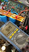
measuring rail-to-rail after the bias on all four have been adjusted. a little more breathing room for the 50v power caps.

aea 620 - 46.jpg
and now lets rev the motor to see if this vintage sports car is ready for track day. keep in mind that the vu meter is accurate for 8r speakers/load vs the 4r 200w dummy load connected. blurry scope numbers dont help...

Vpp= 134
Vrms= 45.6
load= 4r 200w (8r//8r at 100w each)

now calculate V^2/R (Vrms and load) to see a lovely capable number, not to mention the clean looking 100hz wave form.

and yes, the clipping/distortion LED's in the upper right corner of each vu meter are indeed functional.

*photo was captured after the single shot scope mode triggered and the camera shutter caught the needle as the volume was being turned down. trying not to burn up fuses when testing max useable output.
 
aea 620 - 40.jpg
after max testing the right channel, left was already cooling down. testing each channel separately as not to kick a circuit breaker.

aea 620 - 47.jpg
signal generator feeding 5.1vpp or ~1.80vrms at 100hz. dummy load making use of scrap rotel integrated amp multi-channel banana binding posts. having stackable banana cables also helps.
 
aea 620 - 48.jpg
better photo of the left channel output test numbers 134/45.6. right channel had slightly lower numbers, pot resistance for R-ch is slightly higher vs L-ch until about 95% volume.

replacing the volume pot with something newer is messy but possible although deleting the pot completely would be ideal since most systems typically use a preamp vs streamer (as volume control) direct drive. it isnt difficult to push the reset button or turn off power momentarily to change amp input cables or whatever.

aea 620 - 51.jpg
at 48.1v clipping starts to occur although this is a single-shot mode wave form. chances are 47v rms is when clipping begins which would be 552.25w into 4r vs the measurement at 578.40w but this is still just a guess since the amp is already home and no further follow-up measurements can be done.

this concludes the deep dive into the aea analogue 620 amp (a-620 or 620 or the brute). analog engineering associates in maryland definitely created a monster with only a few rough edges that can be optimized to achieve extended longevity. who knows, maybe even crack the century mark after the first service interval.
 
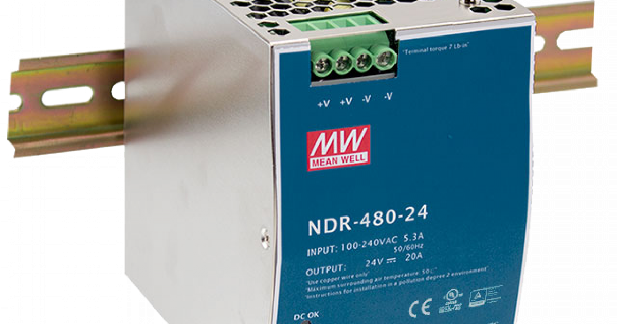
a few lingering ideas about a txf delete mod will be sitting on the shelf. installing a pair of 48v din rail mount smps in series plus low velocity active cooling is something to think about, plenty of space. it would reduce chassis weight by more than a little.


difficult part might be if both supply's dont activate at the same time. perhaps a double rail activation/protection circuit would be optimal downstream. also change the power cap values plus reduce overall ripple with a crc design.
 
Back
Top Bottom