• The move to the new server is done. There are some software and database maintenance updates in process. This has us passing the hat around to help out. We appreciate any donations. Seriously, even a dollar helps. The payment page may be found here - https://www.audiokarma.org/support.html

Acurus A250 and starground

In the channel that is getting hot, let the channel heat up and then measure the Vre (bias voltage) for all 8 output transistors. In other words measure across all eight of the large output resistors in the affected channel and record the measured voltage. The easiest way to do this is to put one of your leads on the positive output binding post for that channel then touch your other probe to the top lead of each resistor.
Hi mondialfan
Thank you for your help. I will measure it that way I hope it would read cause the last time I measured when it got hot I turned the music off and tested it then the DMM read 0 mv. This A250 is crazy when I measured immediately after turn on I got reading on left channel
( one probe on R25 other probe on R30 it read 3 mv now ) and on the right channel it read 0 mv. Then I played the music about 5 minutes it’s getting hot to the touch then I turned the music off then measured and got the reading on the left channel 0mv and the right channel read 16.5 mv
 
Wait..... One probe on R25 the other probe on R30 is not the proper way to measure the bias voltage. Unless your measuring from the top side of one to the bottom side of the other.

You should only be measuring across One resistor. One probe on the top side of R25 the other probe on the bottom side of R25 would be the proper way.

An alternate method as I mentioned before is to put one probe in the positive binding post for the channel your measuring. Then touch the other probe to the top side of the emitter resistor to be measured.
Just marked a photo. Only because my English is not that good. But I'll guess the binding post -->(this is the word I don't understand) is the one I marked with a circle :) the rest is checkpoints..
IMG_20180218_211756.jpg
 
E1E932C2-E610-41B4-8CE1-203C2ABB0A22.jpeg
In the channel that is getting hot, let the channel heat up and then measure the Vre (bias voltage) for all 8 output transistors. In other words measure across all eight of the large output resistors in the affected channel and record the measured voltage. The easiest way to do this is to put one of your leads on the positive output binding post for that channel then touch your other probe to the top lead of each resistor.

I turned it on and measured then hooked up the speakers without hooked up the input from the preamp and I noticed it started heating fast then I waited about 10 minutes it got hot to the touch then I unplugged the speakers then measured like you instructed here what it read
 
Last edited:
Wait..... One probe on R25 the other probe on R30 is not the proper way to measure the bias voltage. Unless your measuring from the top side of one to the bottom side of the other.

You should only be measuring across One resistor. One probe on the top side of R25 the other probe on the bottom side of R25 would be the proper way.

An alternate method as I mentioned before is to put one probe in the positive binding post for the channel your measuring. Then touch the other probe to the top side of the emitter resistor to be measured.
Positive speaker connection at the rear of the amp.

I just measured like that red probe to red speaker binding post and black probe to top lead of each emmitor resistor at a time
 
It's possible the bias circuit has an issue. Bias mv's should not increase by much at all as the amp heats up if it's working correctly. The way to check this would be to turn on the amp cold and after about 1 min measure the bias mv's. Then allow the amp to heat up . and reassure the bias mv's.

It should also not heat up any differently with speakers connected/disconnected and no signal.
 
One side is elevated bring that one down to 2 - 3mv for now.

Does it only heat up with the speakers connected?
Yesterday when I first measured without plugging anything it was not heating up
Now I just learned that it is heating up with speakers hooked up even without playing music . When it is cool off I will try turning it on without hook up anything and wait awhile to see if it’s heating up then hook up the input from the preamp to see what happens
Thank you for helping mondialfan
 
Last edited:
One side is elevated bring that one down to 2 - 3mv for now.

Does it only heat up with the speakers connected?
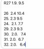
I just want to be cleared. Those readings was from the channel that got hot the other channel read 0 mv
The first numbers was read right after turned on and the second numbers was read after it got hot
 
I just want to be cleared. Those readings was from the channel that got hot the other channel read 0 mv
The first numbers was read right after turned on and the second numbers was read after it got hot

Okay if those were cold and then hot numbers that's too much bias increase from heat. I thought that was one channel versus the other. Usually you'll only see maybe 1mv difference cold to hot.

Does the bias compensation transistor have heatsink compound between it and the heatsink? The bias comp transistor is the very center transistor in the group of the smaller 3 transistors in the middle of the heatsink. Make sure it's tightly against the heatsink too.
 
I found that it is only started heating up after I hookup the speaker to it. I hooked up the speaker to the right channel first both heat sinks still stayed cool but I got reading on right channel about 18.5mv instead of 0mv (when speaker not hookup) I tried turning the pot but it could only went up to 20.8mv could not go down below 18.5mv after I unplugged everything I got about 13.5mv reading and the left heated channel got about 7.5mv except R29 got 9.4mv but it went down to 7.5 in about a minute. Thank you for helping
 
Last edited:
Okay if those were cold and then hot numbers that's too much bias increase from heat. I thought that was one channel versus the other. Usually you'll only see maybe 1mv difference cold to hot.

Does the bias compensation transistor have heatsink compound between it and the heatsink? The bias comp transistor is the very center transistor in the group of the smaller 3 transistors in the middle of the heatsink. Make sure it's tightly against the heatsink too.
The screws on all transistors are tight I could see the excess white grease around all those transistors. Thank you
 
The fact it only starts heating up with the speaker connected is very odd. You said that DC offset measured at the speaker outputs is 0mv is that still correct?
Have you used your meter to measure the resistance of the speaker that you are connecting to the channel that is heating up? If its an 8ohm speaker it should probably measure somewhere in the 6 - 8 ohm range.
 
It just dawned on me what is likely going on. Your amp is probably oscillating, well the channel that is heating up anyway. The fact that connecting a speaker causes it ti heat up tells me that either the speaker is an extremely low resistance or the amp is going into oscillation when a load is connected. These amps are normally quite stable, but if work has been performed on it then there could be issues related to that.

You should verify that the output zobel resistor has not burnt up and opened, it is R34 near the speaker output wiring on the board and should be 1.5ohm. If it shows signs of heating or if the film cap C15 right next to it is melted then the zobel got hot due to oscillation at some point.

If this is the case then a oscilloscope will be an almost absolute necessity to ensure this issue is corrected.
 
Binding post: of course it's the speaker output!:p
Couldn't sleep and thought about the schematic, when I realized what the binding post were in the middle of the night. :rolleyes::rolleyes::rolleyes:

God day
 
It just dawned on me what is likely going on. Your amp is probably oscillating, well the channel that is heating up anyway. The fact that connecting a speaker causes it ti heat up tells me that either the speaker is an extremely low resistance or the amp is going into oscillation when a load is connected. These amps are normally quite stable, but if work has been performed on it then there could be issues related to that.

You should verify that the output zobel resistor has not burnt up and opened, it is R34 near the speaker output wiring on the board and should be 1.5ohm. If it shows signs of heating or if the film cap C15 right next to it is melted then the zobel got hot due to oscillation at some point.

If this is the case then a oscilloscope will be an almost absolute necessity to ensure this issue is corrected.
I would also check the speaker with a meter also. Just to be sure it isn't a speaker a bad winding. Although I do no see the speaker should be able to course that big amount of heat.
 
Last edited:
Do you guys happen to know of a suitable replacement power switch? Mine is flickering to the point that it’s rarely actually on anymore.


Sorry just realized you posted this question.

While there are switches that will fit in the faceplate of the Acurus amps there are no exact replacements for the factory switch.
When I perform an upgrade on an Acurus amp I will disassemble the switch and replace the neon indicator lamp with an LED. This change requires a new wire harness to connect the LED to the transformer secondaries and an appropriate current limiting resistor. Disassembly of the switch is a pain and reassembly is even worse... To disassemble it the rocker comes out of the front of the switch body by prying the sides of the switch apart enough to let the rocker come free. There are two small contacts and a pair of springs inside of it which will fall out. Getting everything lined back up while reinserting the rocker is a nightmare. I've done about 30 of these switches and it still takes me 1 - 2 hours to do one.

This can be done but it is not for the non-mechanically inclined people out there. I will warn you now,,,,THERE IS A GOOD CHANCE YOU COULD RUIN THE SWITCH TRYING TO PERFORM THIS WORK. I'm always on edge while working on one of these switches because if I break it on a customers amp I'll have to pull a switch out of my few loaner amps I have sitting around. The rocker is held in by two small plastic prongs which could easily break either while disassembling or reassembling the switch. If either one of these prongs breaks the switch is trash. As I said before upon reassembly getting the two small springs to sit on their perch while getting the rocker inserted into the switch housing takes a LOT of patience.
 
It just dawned on me what is likely going on. Your amp is probably oscillating, well the channel that is heating up anyway. The fact that connecting a speaker causes it ti heat up tells me that either the speaker is an extremely low resistance or the amp is going into oscillation when a load is connected. These amps are normally quite stable, but if work has been performed on it then there could be issues related to that.

You should verify that the output zobel resistor has not burnt up and opened, it is R34 near the speaker output wiring on the board and should be 1.5ohm. If it shows signs of heating or if the film cap C15 right next to it is melted then the zobel got hot due to oscillation at some point.

If this is the case then a oscilloscope will be an almost absolute necessity to ensure this issue is corrected.

My speakers measured 4 ohm and other speaker 4.9 ohm. I tested with 2 different pairs thank you for all the help
 
It just dawned on me what is likely going on. Your amp is probably oscillating, well the channel that is heating up anyway. The fact that connecting a speaker causes it ti heat up tells me that either the speaker is an extremely low resistance or the amp is going into oscillation when a load is connected. These amps are normally quite stable, but if work has been performed on it then there could be issues related to that.

You should verify that the output zobel resistor has not burnt up and opened, it is R34 near the speaker output wiring on the board and should be 1.5ohm. If it shows signs of heating or if the film cap C15 right next to it is melted then the zobel got hot due to oscillation at some point.

If this is the case then a oscilloscope will be an almost absolute necessity to ensure this issue is corrected.
I will check those and the rest of the board this weekend. I noticed that the excess thermal grease is looking very clean and bright white with no dust on it or very little that when looking down the space between the heat sink and the amp board you don’t see much dust on them
 
Back
Top Bottom