

You are using an out of date browser. It may not display this or other websites correctly.
You should upgrade or use an alternative browser.
You should upgrade or use an alternative browser.
Acurus A250 and starground

KNielsen
Well-Known Member
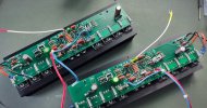
The Acurus A200 poweramplifier has been power up with dim bulp and straight AC, and so far everything OK.
I haven't tested it yet, only checked DC-offset, BIAS and measured voltages different places across the outputstages.
The targets match the outcome.
It's been recap'ed with Nichicon ES Muse and Panasonic ECWF(a)/250V within same capacity. Only the 0.1uf at the input has been raised to 0.47uf as these will fit from the ECWF(a)-series where the WIMA 0.1uf used to be.
Dale RN60D resistors used in line with the signal and at the constant current sources, and R7/14.
At the constant current source the 1N4148 diodes has been replaced with single 1.96Vf/2mA-type green LED-diodes and the current from each CCS is set to 2mA pr side.
The ZTX pre-drivers is removed and TTA/TTC transistors installed as described and shown by @mondialfan previous in this thread, each with their own heatsink on the PCB. The original ZTX is paralleled and I measured 3.2mA pr device, or 6.4mA in total from these units before desoldering. The TTA/TTC do 10.5mA pr unit with the 82ohms in parallel. 9mA might work better, and possibly reduce overshoot on squarewawes, we'll see.
As for the added decoupling caps I went with Elna Silmic ll 47uf/100V and ECWF(a) 0.47uf/250V, where C17 needed a jumper as shown in post #899 page 45 to make direct contact to the rail after the fuse.
I do have Nichicon KZ Muse 100uf/100V that could have been used, but I do think these are much darker sounding then my liking.
I selected the Silmic's for a bit more finesse and do believe these are a better match for the A200 over the KZ-series.
Of course 100uf Silmic's would have been even better, but hard to source. I had 50pcs in stock of the 47uf Silmic's. Now 46pcs in stock
Finally new thermal paste and insulation pads, new fuses ect ect ect..
All cleaned up.
Only thing I didn't change (witch I normally always do) was the 1Kohm BIAS pot... The ones I had didn't fit the A200 as the PCB layout is different from the A250, and I hadn't noticed when ordering parts. The original pots are quite touchy but managed to find the 6mV BIAS-point without much drama.
Testing tomorrow
I haven't tested it yet, only checked DC-offset, BIAS and measured voltages different places across the outputstages.
The targets match the outcome.
It's been recap'ed with Nichicon ES Muse and Panasonic ECWF(a)/250V within same capacity. Only the 0.1uf at the input has been raised to 0.47uf as these will fit from the ECWF(a)-series where the WIMA 0.1uf used to be.
Dale RN60D resistors used in line with the signal and at the constant current sources, and R7/14.
At the constant current source the 1N4148 diodes has been replaced with single 1.96Vf/2mA-type green LED-diodes and the current from each CCS is set to 2mA pr side.
The ZTX pre-drivers is removed and TTA/TTC transistors installed as described and shown by @mondialfan previous in this thread, each with their own heatsink on the PCB. The original ZTX is paralleled and I measured 3.2mA pr device, or 6.4mA in total from these units before desoldering. The TTA/TTC do 10.5mA pr unit with the 82ohms in parallel. 9mA might work better, and possibly reduce overshoot on squarewawes, we'll see.
As for the added decoupling caps I went with Elna Silmic ll 47uf/100V and ECWF(a) 0.47uf/250V, where C17 needed a jumper as shown in post #899 page 45 to make direct contact to the rail after the fuse.
I do have Nichicon KZ Muse 100uf/100V that could have been used, but I do think these are much darker sounding then my liking.
I selected the Silmic's for a bit more finesse and do believe these are a better match for the A200 over the KZ-series.
Of course 100uf Silmic's would have been even better, but hard to source. I had 50pcs in stock of the 47uf Silmic's. Now 46pcs in stock
Finally new thermal paste and insulation pads, new fuses ect ect ect..
All cleaned up.
Only thing I didn't change (witch I normally always do) was the 1Kohm BIAS pot... The ones I had didn't fit the A200 as the PCB layout is different from the A250, and I hadn't noticed when ordering parts. The original pots are quite touchy but managed to find the 6mV BIAS-point without much drama.
Testing tomorrow
Last edited:
KNielsen
Well-Known Member
All sinewaves did good from 100hz-100kHz. No oscillations or artifacts spotted at 100kHz, so I thought I were home safe, more on this below..
1kHz squarewave looks good with a very so slightly overshoot as mentioned in the post above that could happen with the TTA/TTC. But really no biggie...
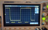
Pictured is the 10kHz squarewave that did surprise me with some ringing mostly in the negative half of the squarewave. Right channel is shown here as this were the one most pronounced. Left channel rings far less but still visible at the negative side on the oscilloscope also.
I'll turn my attention to the 0.47uf decoupling and see what happens later.
FFT showed a spike in the MHz-range, and it might be the 0.47uf resonating.
Best regards
1kHz squarewave looks good with a very so slightly overshoot as mentioned in the post above that could happen with the TTA/TTC. But really no biggie...
Pictured is the 10kHz squarewave that did surprise me with some ringing mostly in the negative half of the squarewave. Right channel is shown here as this were the one most pronounced. Left channel rings far less but still visible at the negative side on the oscilloscope also.
I'll turn my attention to the 0.47uf decoupling and see what happens later.
FFT showed a spike in the MHz-range, and it might be the 0.47uf resonating.
Best regards
KNielsen
Well-Known Member
Problem solved. Same channel shown at 10kHz as previous post:

Change of P2P wire used between the decoupling caps did wonders, I never encountered this before. Initially I removed the small C-bypasses to get the last sorted. If they only work with C16 limited by the internal R in the fuse as original, I do not see the point in adding 0.47uf to the PSU.
Afterwards I lowered the CCS current from 2.05mA to 1.97mA and upped the paralleled resistance to the TTA/TTC from 41.25 ohm to 47ohms, removing the minute overshoot at 1kHz squarewave. The pre-drivers do 8.5mA now, with a more decent heatsink temperature.
The output into 8ohms hasn't changed form the first testings before soldering.
316watts@1kHz
Change of P2P wire used between the decoupling caps did wonders, I never encountered this before. Initially I removed the small C-bypasses to get the last sorted. If they only work with C16 limited by the internal R in the fuse as original, I do not see the point in adding 0.47uf to the PSU.
Afterwards I lowered the CCS current from 2.05mA to 1.97mA and upped the paralleled resistance to the TTA/TTC from 41.25 ohm to 47ohms, removing the minute overshoot at 1kHz squarewave. The pre-drivers do 8.5mA now, with a more decent heatsink temperature.
The output into 8ohms hasn't changed form the first testings before soldering.
316watts@1kHz
Last edited:
KNielsen
Well-Known Member
One thing I forgot to mention, DC-OFFSET....
As I altered the CCS and added new matched 10ohm's to the diff, DC might be better or s**t(!), especially if the CCS isn't within specs for each side.
Before soldering the amp did 4mV and 8mV between the channels, now it's 5mV for both channels.
As I altered the CCS and added new matched 10ohm's to the diff, DC might be better or s**t(!), especially if the CCS isn't within specs for each side.
Before soldering the amp did 4mV and 8mV between the channels, now it's 5mV for both channels.
KNielsen
Well-Known Member
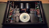
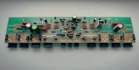
Latest projekt for my living room, all new parts, wirring, fuseclips ect..., all matched the best I can do. Pre-test gave an offset of 1mV pr channel.
I've had this amplifier for ages in the closet last used in a bi-amping setup around 2015-2016 if I remember correctly.
It still needs futher testing before it's plugged into my main system but wanted to share the build at this point.
All in mattblack new paint, and the rest is polished to high finish.
Decoupling caps are raised from the normal used value of 100uf to 220uf. The feedback/input rolloff has been lowered quite a bit, current sources has been altered and of course other predrivers. The new Input signalcable is also with screen to chassis ground.
I'm quite excited to hear the outcome hopefully in near future
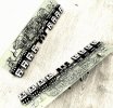

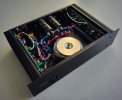
Regards
I've had this amplifier for ages in the closet last used in a bi-amping setup around 2015-2016 if I remember correctly.
It still needs futher testing before it's plugged into my main system but wanted to share the build at this point.
All in mattblack new paint, and the rest is polished to high finish.
Decoupling caps are raised from the normal used value of 100uf to 220uf. The feedback/input rolloff has been lowered quite a bit, current sources has been altered and of course other predrivers. The new Input signalcable is also with screen to chassis ground.
I'm quite excited to hear the outcome hopefully in near future
Regards
Last edited:
KNielsen
Well-Known Member
Testing went well. No oscillation or ringing. Picture shown is 100Hz/1kHz/10kHz squares.


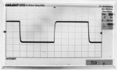
All transistors are new as mentioned in the post above. This amp was test-subject for the main build on page one, and was badly damaged after following an online advice regarding groundlayout. This was before I've purchased an oscilloscope to see the impact of the work performed
Substantial damaged and noisy diff transistors left in the amp, I desided to go with the following for my build:
-Onsemi KSP42/92 cascode
-Onsemi KSA992F/KSC1845F CCS
-Onsemi KSA992F/KSC1845F Diff-pairs
-Toshiba TTA006B/TTC011B Predrivers
-Profusion 2SA1837/2SC4793 Drivers
-Onsemi KSC3503D BIAS
-Onsemi MJL1302/MJL3281 Outputs
BIAS holds stable and I haven't found any problems swapping the original transistor and leave the BIAS circuit with original values. I did look towards the Aragon 8008 schematic when swapping the transistor, but decided to test in original state as pr Acurus A250 layout and values. Works great.
The CCS is set to 1.926mA pr side using TLLG4400 2mA-type diodes and R5 and R12 is 649ohm. R4 is 200Kohm leaving roughly 830uA through each diode. Well within specs. I did have to recalculate the CCS R5/12 as the Vdrop across the new KSA992/KSC1845 is different from the original MPSA42/92, but no big issue. Just an FYI if someone tries to implant the above diodes and values.
Rails are right on 86VDC, output is 335watts into 8ohm.
Offset is stable at 2mVDC.
Best regards
All transistors are new as mentioned in the post above. This amp was test-subject for the main build on page one, and was badly damaged after following an online advice regarding groundlayout. This was before I've purchased an oscilloscope to see the impact of the work performed
Substantial damaged and noisy diff transistors left in the amp, I desided to go with the following for my build:
-Onsemi KSP42/92 cascode
-Onsemi KSA992F/KSC1845F CCS
-Onsemi KSA992F/KSC1845F Diff-pairs
-Toshiba TTA006B/TTC011B Predrivers
-Profusion 2SA1837/2SC4793 Drivers
-Onsemi KSC3503D BIAS
-Onsemi MJL1302/MJL3281 Outputs
BIAS holds stable and I haven't found any problems swapping the original transistor and leave the BIAS circuit with original values. I did look towards the Aragon 8008 schematic when swapping the transistor, but decided to test in original state as pr Acurus A250 layout and values. Works great.
The CCS is set to 1.926mA pr side using TLLG4400 2mA-type diodes and R5 and R12 is 649ohm. R4 is 200Kohm leaving roughly 830uA through each diode. Well within specs. I did have to recalculate the CCS R5/12 as the Vdrop across the new KSA992/KSC1845 is different from the original MPSA42/92, but no big issue. Just an FYI if someone tries to implant the above diodes and values.
Rails are right on 86VDC, output is 335watts into 8ohm.
Offset is stable at 2mVDC.
Best regards
Last edited:
KNielsen
Well-Known Member
FINAL THOUGHTS AFTER FIRST LISTENING SESSION:
If money is no option, this is the build I would recommend others for their A250. The cost of parts is what it is, with the outputs as the ones that blows most budgets as more then needed have to be ordered to make good pairs, and not to mention the hours that's going into matching these if you gotta pay an electrician to do the work. The rest is as is, just a few adjustments in values. Most people I've built for want Dales throughout anyway, so.....
Besides from the outputs the chassis rebuild and groundplane takes quite an effort and measuring before drilling and cutting. Time-consuming but spent well to make the build look as proff as possible.
I split some of the grounds as i did in my build at page #1, so speaker_GND / amp_GND / signal_GND are all seperat and only meet at the center point at main groundplane, coupled with the most noisy grounds closest to the centertap / chassic_GND and finishing of with signal_GND as the last. This works excellent in A250.
I've got absolutely zero hum from speakers or transformer and no hizz from the top. The screened interconnect to chassic_GND seams to help this matter also.
I lowered the cutoff point and used overkill big input cap from the Muse UES-series. The amp does do a note deeper, but at first stroke I instantly thought "direct coupled amplifier". I cannot hear the impact of a capacitor anymore, and the reduced ESR by using bigger caps might be a plus.
Regarding the CCS I added low voltage cap across the diodes. Under normal operating I cannot see this mod performing on my oscope, but reaching clipping the amp does is so much smoother then without these installed.
I tried it in my preamp and found that the mids did benefit. I haven't A/B-tested this in Acurus A-series but the soundstage is just as expected from my preamp,, smooooth......!
The decoupling used are Chemi-con KZN, and since Silmic ll are becoming hard to source these KZN are the closest match yet to my ears yet when used in Acurus without fatigue or favour in the top or bottom spectrum. The Nichicon Muse (polar type) tend to favour the lower end frequencies and quite dominating, witch I do not like in amplifiers. This is the job for different speakers by choice and listening room.
Soundwise the A250 build is neutral and easy listening. It just plays without effort.
Best regards // and hope this will inspire others although this thread has died a long time ago.
K.Nielsen
If money is no option, this is the build I would recommend others for their A250. The cost of parts is what it is, with the outputs as the ones that blows most budgets as more then needed have to be ordered to make good pairs, and not to mention the hours that's going into matching these if you gotta pay an electrician to do the work. The rest is as is, just a few adjustments in values. Most people I've built for want Dales throughout anyway, so.....
Besides from the outputs the chassis rebuild and groundplane takes quite an effort and measuring before drilling and cutting. Time-consuming but spent well to make the build look as proff as possible.
I split some of the grounds as i did in my build at page #1, so speaker_GND / amp_GND / signal_GND are all seperat and only meet at the center point at main groundplane, coupled with the most noisy grounds closest to the centertap / chassic_GND and finishing of with signal_GND as the last. This works excellent in A250.
I've got absolutely zero hum from speakers or transformer and no hizz from the top. The screened interconnect to chassic_GND seams to help this matter also.
I lowered the cutoff point and used overkill big input cap from the Muse UES-series. The amp does do a note deeper, but at first stroke I instantly thought "direct coupled amplifier". I cannot hear the impact of a capacitor anymore, and the reduced ESR by using bigger caps might be a plus.
Regarding the CCS I added low voltage cap across the diodes. Under normal operating I cannot see this mod performing on my oscope, but reaching clipping the amp does is so much smoother then without these installed.
I tried it in my preamp and found that the mids did benefit. I haven't A/B-tested this in Acurus A-series but the soundstage is just as expected from my preamp,, smooooth......!
The decoupling used are Chemi-con KZN, and since Silmic ll are becoming hard to source these KZN are the closest match yet to my ears yet when used in Acurus without fatigue or favour in the top or bottom spectrum. The Nichicon Muse (polar type) tend to favour the lower end frequencies and quite dominating, witch I do not like in amplifiers. This is the job for different speakers by choice and listening room.
Soundwise the A250 build is neutral and easy listening. It just plays without effort.
Best regards // and hope this will inspire others although this thread has died a long time ago.
K.Nielsen