• The move to the new server is done. There are some software and database maintenance updates in process. This has us passing the hat around to help out. We appreciate any donations. Seriously, even a dollar helps. The payment page may be found here - https://www.audiokarma.org/support.html

Acurus A250 and starground

Off-topic:
My Aragon/Acurus inspired amp is stable!
No DC-servo or feedback cap in circuit right now when I succeed after hundreds of trail/errors, only a 1Kohm to ground after the main diff-sektionen for now.
I've added a DC-OFFSET adjustment on a breadboard earlier this day, and worked perfectly:)
Every time I've got a signal passing through, the oscope did to lines, like the NPN/PNP-outputs were out of fase. The position of 1N5408-diodes were the issue, and now hardwired P2P.
I still do low voltage ±32VDC, and some values are adjusted accordingly for now, but finally some testing can begin.
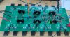
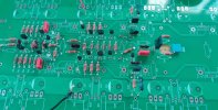
IMG20230612151725~2.jpg
Best Regards

EDIT: Sooooryyyy... To early, spotted a small misbehave:oops: but so close...
 
Last edited:
  • Like
Reactions: Six
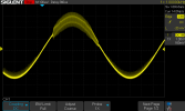
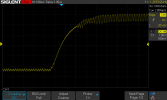
Small signaltest last evening, not good (!):
1kHz
SDS00001.pngSDS00002.png
SDS00003.png
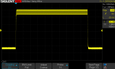
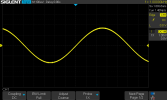
Same signal after some soldering today:
1kHz_sine.png1kHz_square.png

Looking really close at the last square wave, the top half shows some noise or drift. Adjusting the BIAS slightly removes this noise while signal is applied, but I haven't had time to dig further into this. But I have some good clues, as the BIAS starts at around 13mV at the emitter when the circuit is powered up, and as I adjust the pot the BIAS will drop to around 6mV and later raise again. In the first half cycle, the oscope shows quite a lot of noise, until the "real" BIAS emerging. So not stable, or at least I need to rethink the resistors here.

I did end up with a feedbackcap for the last signals to emerge, and looked at the Acurus A250 position of the 1N4148 diodes to make it stable as a "quickfix" to get things going.
-But I'll try with a servo again later on.
In my first proto I forgot to adjust the resistor value at the 1N5242b diodes accordingly to the ±32VDC test conditions, so the servo never saw even a few volts ;) ooops..

I have tried the KSA1381/KSC3503 that are available on the market as predrivers, but the D and E classification between the two is not good. I did try to find some descent couples where Hfe wasn't to far apart, but didn't succeed in circuit. The Toshiba TTA006/TTC011 seams to work with minor adjustments :)

At idle, 12.2mV over the 0.47ohm emitter (26mA), the DC-OFFSET is 3mV so far, so quite good starting point for a dual diff.
A week ago I had roughly 60mV offset, mainly due to poor match between the 1N5242B, and some poor choices regarding my ground layout to begin with (now solved P2P). I took the time to find best suitable pairs, matched at the mA they should work within, and the first diff-section is now maximum 0.1mV offset. This stage will be amplified quite a bit later on, so lesson learned :)

LTP is set to 4mA, 2mA pr transistor in the second diff. The predrivers will see 10mA with 47ohm, full ±80V rails, so I might lower the LTP if heat becomes a problem.

Regards

EDIT: should be mentioned that I added 47/0.1uf decoupling at the rails for both signals from last evening and today's testing. One set pr transistor. I might do this part over, as I've seen better results with 100uf, and may be fewer on the finish board.
 
Last edited:
  • Like
Reactions: Six
Second set of scope traces looks a lot better. Looks like you're making good progress....
Ever since the first drawing in 2020 I've been keen to seperat powergrounds and signalground. This week I discovered it didn't work on this one!;) So yes, now I'm progressing after cutting some traces and rearrange:) Should have done this year's ago.....
-Most of the problems is due to layout I think. It's quite hard to rid of even small amount of swing, and at some point I think I've been to generous with wide long tracks. Some part of the circuit might act like an antenna, other parts simply have to long run, even though the traces are wider. I believe the distance between drivere and predriver is to big, but hard to prove with this layout other then I've seen some reduce of swing even by adding hardwire P2P between the drivers. Now there is 220pf across the "Q15/16" and 10pf across "R27" (look at the 8008 schematic) helping alot.
The Kicad-forum surgested that I hatched (a coppertrace looking like a fine masked net) the ground plane due to size, to stop most of the possible swing in the layout, doing this calls for a third layout since I neglected this option before ordering this draw of the PCB.
But the results is getting better and better:)
 
Last edited:
Just a last word on this one:
This is a testlayout, based on the notes I make through the findings on the scope the last week.
The predriver is center with the drivers and then outputs right next to it.
D11/D12 is misplaced on this photo since I've learned that these cannot be in between one or the other polarity of the output transistors, so they have to be moved to either end of the PCB.
Ground plane is also not complete yet, as it's not merging on the PCB right now, but it's hatched.
I've added via's to the rails between the transistors and decoupling to help some heat dissipation before this ends in the caps. At the end I'm unsure to stick with the amount of decoupling... I do recall that 2x100uf pr rail did alot better then 8x47uf pr rail. Sadly I didn't save the picture on the scope, so have to retry this one...
The two holes at each end of the board is just a thought, adding some thermal protection for cutoff if needed.
BIAS is still center.
At the end it's a tough layout getting right, without compromise. Reading alot of threads on DIYAudio, I'm definitely not the first one to rub my head on this topology :)
I did another draw where all pre/drivers/BIAS is center on the PCB, in close contact for good biasing. But this calls for other problems in layout.....
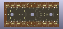
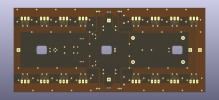
X8_front.pngX8_back.png
 
Last edited:
At the end it's a tough layout getting right, without compromise. Reading alot of threads on DIYAudio, I'm definitely not the first one to rub my head on this topology
Hi Knielsen, I am following your progress with much anticipation. Would you be willing to share what your design goal specifications are, and how they improve on what you’ve already achieved by modifying the Acurus A250 boards and power supply?

I admire what you’ve shared as a leaning exercise, and expect the new design will incorporate many of the improvements made by later Acurus/Aragon models such as Left/right mirrored layouts, improved ground and PSU configurations, etc.

I am not experienced enough to visually identify how or where you’ve made enhancements on your new design, so I would love to see how you approached each section, and how it differs from: 1) the existing Acurus boards, and 2) how the results of each iteration helped you identify issues and improve performance. (You’ve already done that to a great extent - just looking to understand specific tweaks in relation to the overall strategy)

For my part, I have recently purchased a second non-working A250, ($190) hoping to refurbish my two amps to biamp my front speakers… my process is very slow due to other projects, so I appreciate this thread for its educational and motivational aspects.

Keep up the good work!
Six - Minneapolis
 
@Six the goal is to try and succeed, that's it!:) and would love this amp in my living room if I do so...
To begin with I had all sorts of thoughts about high power ect ect, but now it's for the fun and learning. Initially it's an 8008 with some adjustments, about ±80V rails and output within that range. LTP is raised, but I don't know the outcome of the state yet, as the predriverstage will be 10-11mA and the drivers around 20mA. This do call for devices mounted on the main heatsink, at least the drivers (look at the layout in the picture, quick draw last evening, so not finished, but overcomes all my previous findings at least on paper?!).....
As for the LTP, where I really wanted LED's instead of 1N4148, I found partnumber WP710A10LZGCK on Mouser to be exactly what I needed, 2.65fV/2mA-type. Stable cold operation at low current, 4-500μA, more about this later....
-That said, it's a tough one. I believe my layout still suffers from ground loops, coursing all sorts of problems, mostly unstable rails! So untill this is fixed, I'm on a stall for further testing;)

I will share the project if I succeed, answering most of your questions, PCB files and schematic with all info included:)
Regarding my Acurus, your questions should be answered the first 10-15 pages here.. Skip the hole section about my thoughts on starground;)

I do read alot of articles on subject, but tend to learn more seeing it on the scope afterwards.. As for beginners knowledge, I can recommend some of the videos by user W2AEW on YouTube, who's very good at explaining the workings of transistors ect ect.
Also, there is a very simple simulator called "EveryCurcuit", both available on mobile and PC, that somewhat can help in the right direction without being an engineer.

Through my previous writings here I see my own progress; and I have learned through the years. But there is still lots I don't know the answer to:)

Good day

Regards
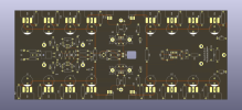
X8 front2.png
 
Last edited:
I forgot your original sizing for the board. What heatsink do you plan on mounting this on?
This is the chassis I want to use. 400x200mm profiles.

The board's total dimensions including output transistors is 320x180mm (approx 12.5x7").
I did this layout to seek a more enen use between the thermal mass of heatink and transistors. Don't know if this has any reel benefits in real world, but that's the thought.

Also, I have a good pile of 'Fischer sk104 25.4mm high' heatsink in my inventory, and they seams to do the job quite good at the predrivers.

Regards
 
I need some help. I'm quite sure groundloops are some of my main problems... DC-OFFSET can be quite different depending on my P2P on the groundpath, and also the stability of the rails witch is quite unpredictable.

I just need to know, so I can just leave at least this one out: Page 6 in the attached, the GND connection isn't connected with wire to common "starground at PSU", right?
I read it as; only XLR connection see the +/-/gnd, and all other grounds including signalground runs at the PCB in an order to sort noize out, before a main ground wire to PSU. The last comment about the order of run, is my belief. The 8008 pictures online surgest this approach.

I test with RCA, and connect this to +/GND at the board

Thanks:)
//Regards
 

Attachments

After a big break from my project, I decided to start from scratch on a new board.
Build in sections for better testing as progressing on each stage.
I should have done this to begin with as this makes troubleshooting far easier in unknown territory with a homedrawn PCB, I think.
The first and second inputstage is working flawlessly, at this point 0.8mV DC-offset, only with a 1Kohm to ground. No servo or cap installed yet.
Continuing build with the predriver stage, the scope showed the first signs of swing and offset bumped up above 100mV.
I used 10pf across B and C at the predrivers (Aragon 8008 uses 5pf) in the first build, and so far it looks like these is far from enough with this new more restricted "build method". Swing was instant..
Sadly I only had 220pf in stock, but tried these much bigger values anyway. The swing is gone for now, and hopefully also will not be present when next stage is built.
I'll have to order a bunch of different pf-values, and find the best suited:)
 

Attachments

  • IMG20230712153814~2.jpg
    IMG20230712153814~2.jpg
    109.2 KB · Views: 9
Last edited:
  • Like
Reactions: Six
Btw: I'm doing all pre-test with a ±32VDC digital powersupply, mainly due to the relay protection this offers with more advance settings for maximum current cutoff ect... Could this be the problem, that I don't have enough voltage..? It's not a problem on an A250 circuit in bench, but I newer tried ±32VDC on Aragon where the predriver section is built a bit different for Acurus...???

Looking at the Aragon 8008 schematic (the new version) I know I have to lower the two 10Kohm cathode resistors (I think this is called) to 3.32Kohm to get some useable ~±11.30VDC at the first input/servo-supply. That makes me wonder if other stages suffers to, and I haven't spotted this due to low voltage.

Regards
 
Last edited:
Btw: I'm doing all pre-test with a ±32VDC digital powersupply, mainly due to the relay protection this offers with more advance settings for maximum current cutoff ect... Could this be the problem, that I don't have enough voltage..? It's not a problem on an A250 circuit in bench, but I newer tried ±32VDC on Aragon where the predriver section is built a bit different for Acurus...???

Looking at the Aragon 8008 schematic (the new version) I know I have to lower the two 10Kohm cathode resistors (I think this is called) to 3.32Kohm to get some useable ~±11.30VDC at the first input/servo-supply. That makes me wonder if other stages suffers to, and I haven't spotted this due to low voltage.

Regards
Sounds like you've got a solid approach to debugging the new board. I don't know if 32 volts is not enough for the Acurus, but I have a Variac that I bought used for about $50 which allows me to "Dial-in" the AC voltage going to the actual transformer (including increasing the voltage available at the wall outlet by about 10%) That's how I test new amps, also using the dim-bulb tester.

Six.
 
I'd like to check with the Acurus A250/A200 experts to ensure I've interpreted the dual-mono PSU layout correctly, and also ask if there is really any benefit to the (simplified) Aragon 4004 scheme that has dual-secondaries feeding 4 rectifiers and 4 capacitors, (I'm estimating it would be significantly more expensive to buy a new transformer with dual-secondaries, or two smaller separate transformers)

Details: I expect the dual rectifier scheme will have less cross-talk between channels than the original version, along with less noise due to the ground-lift, separation of Input grounds from Speaker Return (#761) and also separating the ground path for each channel. Note that even though the drawings show the various grounds tapping-off at different points, they would all come back to the star ground between the two capacitors. (which is typically located at the center of the aluminum or copper bar connecting the (+) terminal of one capacitor to the (-) terminal of its partner. Also note that from post #761, I should have shown two separate wires from each star-ground to a) the RCA input ground and b) the speaker return, and those two terminals should not be tied together as they are in early versions of the A250.
The dual CRC snubber network also in the modified scheme is there to reduce noise, and I'm providing one for each channel, thinking that there may theoretically be different loads for L and R channels (and therefore different rectifier behavior that may cause ringing by the transformer) (PDF). I have also read that due to the potential fault currents, the ground-lift shown on the 4004 layout should be more than just a 5w resistor (recommendation is to use a 35A bridge rectifier for each channel (PDF Link).

To wrap-up, is the modified pseudo dual-mono PSU below enough to get the most out of the Acurus A250 amp boards, or do the 4-rectifiers in the 4004 PSU provide a significant performance boost, even though the overall PSU capacitance is similar to the middle (Modified) scheme? IOW, is the 4004 PSU overkill for the A250 amp boards?

Thanks! Six.... (Gathering supplies, and refreshing my memory on previous research)
PSU Options.jpg
 
Last edited:
Here is how I did the PSU. Just paralled the AC secondary from the transformer to each bridge.

I did the same approach for a friend in his A250, but using 4x16000uf Kemet ALS80 instead of 8x13000uf Kemet ALS70. It sounded great also.

Regards
 

Attachments

Last edited:
is the modified pseudo dual-mono PSU below enough to get the most out of the Acurus A250 amp boards
Yes, I believe so. And there isn't any room for further improvement after the "dual-mono" build anyway. Even a bigger transformer can be tough to fit for more VA.
I've measured severel times, and can't squeeze more in the box.
 
Hi Knielsen, I've been looking for possible replacements to the (5-leg) differential pairs on my A250 (I'm hoping to get a few sets of full replacement parts to last me at least 20 years of repairs :) before more of them become obsolete... as I hear through-hole components are slowly being phased out)

On your new board it looks like you might be using the KSA992/C1845 that Mondialfan originally suggested (on post 430) as replacement to the Diff pairs Q4 and Q11 (originally 2SC1543/2SA798) and you noted having implemented this on post #740. Are these the back-to back transistors labeled Q11/17 and Q12/18 on your new board? I have some questions about this: they appear to be bonded face-to-face (equalize temperature?) with no heatsink (None needed apparently?) my question is what type of adhesive did you use?

Also, it appears that all 6 legs are soldered on-to the board and I realize this is a new design - I found this page that appears to address this issue: Replacing 2SA798 is this the solution you have implemented on previous fixes, and how I could implement on my A250?

Thanks - Six

1690058283306.png
 
Hi Knielsen, I've been looking for possible replacements to the (5-leg) differential pairs on my A250 (I'm hoping to get a few sets of full replacement parts to last me at least 20 years of repairs :) before more of them become obsolete... as I hear through-hole components are slowly being phased out)

On your new board it looks like you might be using the KSA992/C1845 that Mondialfan originally suggested (on post 430) as replacement to the Diff pairs Q4 and Q11 (originally 2SC1543/2SA798) and you noted having implemented this on post #740. Are these the back-to back transistors labeled Q11/17 and Q12/18 on your new board? I have some questions about this: they appear to be bonded face-to-face (equalize temperature?) with no heatsink (None needed apparently?) my question is what type of adhesive did you use?

Also, it appears that all 6 legs are soldered on-to the board and I realize this is a new design - I found this page that appears to address this issue: Replacing 2SA798 is this the solution you have implemented on previous fixes, and how I could implement on my A250?

Thanks - Six

View attachment 2939886
Yes I'm using 992/1845 as recommended, and works quite well with 100ohm resistor across each emitter for now (can't remember the technical word in English for this resistor!?).. The Hfe is around 400 in the batch I have. I also have CDIL CSA970/CSC2240 witch looks quite good on the oscope, and noise should be lower then 992/1845, but the Hfe is also halved to around 200, so for now I've sticked with the Onsemi-types.
CDIL is 100mV collector current like the original Toshiba 2SA970/2SC2240 instead of 50mV 992/1855, but that's nothing to worry about in the Acurus, and 992/1845 will makes fine replacements.
If you gonna use the 992/1845 in your Acurus just be aware of the common emitter. 2SC1543/2SA798 share the same emitter pinout, that's why it's only 5-leg in the following order BCECB if I remember correctly. 992/1845 is ECB, so you might end up with some serious legbending if you want back-to-back. I would match them closely and place them side-by-side on the PCB with surrounding heatsink on the housing.. You might end up with a better solution then my idea?:)
-The newer A200 has a 6-leg differential with 10ohm at each emitter, so there is some difference in the Acurus lineup depending on age.

As for thermally coupling the TO-92 on the PCB shown I've tried with heatsink, but I didn't see much difference of dc-offset in the setup tested. It does work though for good contact between the two housings.
In my layout, I've made sure that the 992/1845-pair is mounted/soldered close together on the PCB, so I do not have to squeeze them together for a good contact, just solder and job done. In the end I might just give them a dap of glue to keep them thermally bonded :)

EDIT: yes, through holes are a dieing breed. Especially audiophile types are sourced out quite fast. Latest is Nichicon Muse-series and their series of audio SNAP-IN caps that's been set to stop in production.

Regards
 
Last edited:
Yes I'm using 992/1845 as recommended, and works quite well with 100ohm resistor across each emitter for now (can't remember the technical word in English for this resistor!?)..
If you gonna use the 992/1845 in your Acurus just be aware of the common emitter. 2SC1543/2SA798 share the same emitter pinout, that's why it's only 5-leg in the following order BCECB if I remember correctly. 992/1845 is ECB, so you might end up with some serious legbending if you want back-to-back. I would match them closely and place them side-by-side on the PCB with surrounding heatsink on the housing.. You might end up with a better solution then my idea?:)
-The newer A200 has a 6-leg differential with 10ohm at each emitter, so there is some difference in the Acurus lineup depending on age.

As for thermally coupling the TO-92 on the PCB shown I've tried with heatsink, but I didn't see much difference of dc-offset in the setup tested. It does work though for good contact between the two housings.
In my layout, I've made sure that the 992/1845-pair is mounted/soldered close together on the PCB, so I do not have to squeeze them together for a good contact, just solder and job done. In the end I might just give them a dap of glue to keep them thermally bonded :)

Regards
Thank you for confirming and including the detail about the emitter-resistors and pin-out differences. I will get enough of the KSA992/C1845 to find some close matches. I hope to start digging into my amps in the next month or so, as the parts I’ve ordered start arriving.
I do have one flow-up question, the 100r emitter resistor you mention, does it go between the two new 992/1845 emitters to be joined? or after they are soldered together - between Q4/Q8 and Q11/Q1. I don’t see this component on the A250 schematics I have.
Thanks again!
Six.
 
Last edited:
Thank you for confirming and including the detail about the emitter-resistors and pin-out differences. I will get enough of the KSA992/C1845 to find some close matches. I hope to start digging into my amps in the next month or so, as the parts I’ve ordered start arriving.
Six.
Sorry, made an edit while you were posting, but makes no difference for your search;) just mentioned the CDIL types also
 
Back
Top Bottom