

You are using an out of date browser. It may not display this or other websites correctly.
You should upgrade or use an alternative browser.
You should upgrade or use an alternative browser.
Acurus A250 and starground
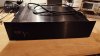
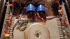

@KNielsen: Great photos, thanks! Looks like you did the transistor mod from Mondialfan’s post #451 and your posts 661 and 667. Could you go into a little more detail, or show a close up photo of how the 1 new transistor replaces the two original ones? (Which legs go into which holes?). Also how the corresponding resistors are paralleled and/or resized? I have seen the schematic, but it looks like in your photo - the transistors are facing opposite from each other.
Thanks again, Sixto.
Thanks again, Sixto.

KNielsen
Well-Known Member
I've just finished the amp for further testing with full AC connected, and didn't take some pictures of the backside of the boards.@KNielsen: Great photos, thanks! Looks like you did the transistor mod from Mondialfan’s post #451 and your posts 661 and 667. Could you go into a little more detail, or show a close up photo of how the 1 new transistor replaces the two original ones? (Which legs go into which holes?). Also how the corresponding resistors are paralleled and/or resized? I have seen the schematic, but it looks like in your photo - the transistors are facing opposite from each other.
Thanks again, Sixto.
Take a look at the TTA/TTC-datasheet and compare it to the ZTX. You'll then realise that some legbending is needed to fit the TT-series.
Emitter from the new TT is connected to both of the 82ohms in parallel, and then bend the legs on B and C to fit. These are palled on the circuit, so just choose which of the holes that makes the best fit for the transistor, and remember some free space for the heatsink.
Mondialfan has posted a new schematic that shows what to do, and I repost here

Regards
Last edited:
KNielsen
Well-Known Member
@Six The build at hand is almost complete. There is some wires that needs attention, but before real 230VAC-testing I'll leave them for now until I'm satisfied, and dear to power it on my own speakers
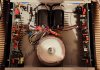
-All caps has been renewed
-0.47uf parallel across D3/D6
-New TTA/TTC-predriver
-100uf/1uf decoupling
-R1/2/3/7/14/18 is RN60D
-R5/R12 is now 300ohm RN60D
-Multiturn pot added
-36000uf/2.7uf PSU, no bleeders
-Powerswitch repaired with new LED and harness (depending on the data from the LED, the resistor should be calculated accordingly, and I use a 1N4007 diode in this stage before the resistor to the LED)
-New signal-ground wire to PSU, with back-to-back diodes and 10ohm/2w according to schematic
-SL32 2R025 inrush limiter
-I've added new white thermal paste and new insulation (if that's the word in English?). The old insulator might be reused, if possible.
-BIAS approx 6-8mV when finished
-All caps has been renewed
-0.47uf parallel across D3/D6
-New TTA/TTC-predriver
-100uf/1uf decoupling
-R1/2/3/7/14/18 is RN60D
-R5/R12 is now 300ohm RN60D
-Multiturn pot added
-36000uf/2.7uf PSU, no bleeders
-Powerswitch repaired with new LED and harness (depending on the data from the LED, the resistor should be calculated accordingly, and I use a 1N4007 diode in this stage before the resistor to the LED)
-New signal-ground wire to PSU, with back-to-back diodes and 10ohm/2w according to schematic
-SL32 2R025 inrush limiter
-I've added new white thermal paste and new insulation (if that's the word in English?). The old insulator might be reused, if possible.
-BIAS approx 6-8mV when finished
Last edited:
Nice summary of the rebuild, thanks! Will be interested to hear if it performs as well as your previous builds. From your experience, is there any audible difference between 2 PSU caps and 4 or more caps if the total uf capacity is within 10%, and cost/labor difference is not a factor? Sixto.
KNielsen
Well-Known Member
First one done. Next up, preamp (not posted here)..
I haven't hooked up the amp yet to my own speakers, should be mentioned..
I lowered the rail voltage from 91.2VDC to 83.2VDC at the expense of high output wattage, but more BIAS. It's the old type xformer (before Mondial realised thet EU was using 230VAC, and not 220VAC or 240VAC), so I can't come closer to 85VDC, but to give it some more BIAS 91.2VDC is to much for most A250's in the long run, also with the new TT-series installed I like the lower rails supply after seeing the curves produced in a modded A200 also with TT installed, and this also reduces some heat on the new heatsink-profiles mounted inside the A250.
Actually I'd end up spending most of the day with the f****ng power switch repair (today it tricked me, more then once!!). It turned out to be a lose connection inside the switch of some sort after replacing the old lamp with an LED, and a pain in the "behind" to fix. The LED functioned when I powered the switch before install, but as soon as the switch were installed in the amp, the LED didn't work.. But,,,,, succes in the end
Sine and squarewaves were perfect on the oscilloscope, and 2x300 into 8ohms/1kHz on 83VDC-rails is quite ok on 230VAC/50Hz European power.
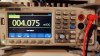
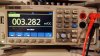
DC-OFFSET remained below 5mV for both channels at 91.2VDC and 83.2VDC rails.
Sound on tomorrow
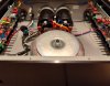
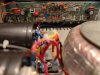
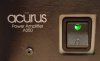
I haven't hooked up the amp yet to my own speakers, should be mentioned..
I lowered the rail voltage from 91.2VDC to 83.2VDC at the expense of high output wattage, but more BIAS. It's the old type xformer (before Mondial realised thet EU was using 230VAC, and not 220VAC or 240VAC), so I can't come closer to 85VDC, but to give it some more BIAS 91.2VDC is to much for most A250's in the long run, also with the new TT-series installed I like the lower rails supply after seeing the curves produced in a modded A200 also with TT installed, and this also reduces some heat on the new heatsink-profiles mounted inside the A250.
Actually I'd end up spending most of the day with the f****ng power switch repair (today it tricked me, more then once!!). It turned out to be a lose connection inside the switch of some sort after replacing the old lamp with an LED, and a pain in the "behind" to fix. The LED functioned when I powered the switch before install, but as soon as the switch were installed in the amp, the LED didn't work.. But,,,,, succes in the end
Sine and squarewaves were perfect on the oscilloscope, and 2x300 into 8ohms/1kHz on 83VDC-rails is quite ok on 230VAC/50Hz European power.
DC-OFFSET remained below 5mV for both channels at 91.2VDC and 83.2VDC rails.
Sound on tomorrow
Last edited:


KNielsen
Well-Known Member
A bit off topic, but I started some drawings about page#20 or so.. It did evolve a bit:
My 16 powertransistor pr channel Acurus/Aragon inspired protobuild (yes it's a mess, for now)...
The design calls for ksp42/92 but quickly ended up using KCA992/KSC1845 so all legs are bend, and some adjustments of mica-caps and resistors. I've started a new drawing from my findings on the proto, to do a final layout for my livingroom with all errors corrected.
Couldn't get it to function stable during longer tests with the DC-servo, and skipped this in favour of a simpel RC-function feedback, witch worked instantly.
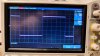
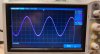
I'm waiting for new powertransistors from same batch for further testing, as those I used wasn't any good from a previous scrapped amplifier, but I did manage to do some pretest before scrapping the transistors from the PCB (measurements shown below, low voltage input signal@1kHz, 64VDC rails in test, 3mV BIAS ). Meanwhile I've added 16x 30ohm/3w across B and E where the output transistors should be, but testing becomes quite boring without the real deal..
Measurements is done with TTA006B/TTC011B pre-drivers. I did order a batch of KSA1381/KSC3503 to try, but they only come in 1381E and 3505D, so Hfe is to far arpart to my liking with these on-semi's after measuring those.
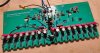
My 16 powertransistor pr channel Acurus/Aragon inspired protobuild (yes it's a mess
, for now)...The design calls for ksp42/92 but quickly ended up using KCA992/KSC1845 so all legs are bend, and some adjustments of mica-caps and resistors. I've started a new drawing from my findings on the proto, to do a final layout for my livingroom with all errors corrected.
Couldn't get it to function stable during longer tests with the DC-servo, and skipped this in favour of a simpel RC-function feedback, witch worked instantly.
I'm waiting for new powertransistors from same batch for further testing, as those I used wasn't any good from a previous scrapped amplifier, but I did manage to do some pretest before scrapping the transistors from the PCB (measurements shown below, low voltage input signal@1kHz, 64VDC rails in test, 3mV BIAS ). Meanwhile I've added 16x 30ohm/3w across B and E where the output transistors should be, but testing becomes quite boring without the real deal..
Measurements is done with TTA006B/TTC011B pre-drivers. I did order a batch of KSA1381/KSC3503 to try, but they only come in 1381E and 3505D, so Hfe is to far arpart to my liking with these on-semi's after measuring those.
Last edited:
KNielsen
Well-Known Member
No thread (yes one, where I questioned my multiple BIAS transistor layoutI was wondering if you were still tinkering with this design… do you also have a thread about it in diyaudio? It’s a nice theoretical exercise, and the waveforms you show seem to be excellent! Keep up the good work!
). I've started one "build progress thread" in a Danish forum, but it quickly became a debate between what people like as circuitry, and not a debate of the circuitry at hand. So I'm enjoying this build myself for now, and a great learning lesson it is!
Last edited:
KNielsen
Well-Known Member
Regarding the posted above:
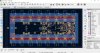
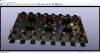
I've started this (maby final drawing????) last evening from my findings so far... So very new draw and far from done.
Minus rail at the bottom, plus rail at the top, so still 16 transistors pr channel. Voltage/power-GND is applied to the left on the board, signal-input/signal-GND is on the right, speaker-out at the bottom (the board can be flipped to fit opposite channel, still speaker-out at the bottom).
By looks I like the proto better, but this layout makes more space for each transistor to "breath" at the heatsink, and a very short signalpath from the amp-input to circuitry, and keeping power/signal apparat.
Also this design makes it easier to do one PCB that'll match and work for both left and right channel, so hopefully only one order of PCB is needed for one amplifier, instead of two PCB's.
I've started this (maby final drawing????) last evening from my findings so far... So very new draw and far from done.
Minus rail at the bottom, plus rail at the top, so still 16 transistors pr channel. Voltage/power-GND is applied to the left on the board, signal-input/signal-GND is on the right, speaker-out at the bottom (the board can be flipped to fit opposite channel, still speaker-out at the bottom).
By looks I like the proto better, but this layout makes more space for each transistor to "breath" at the heatsink, and a very short signalpath from the amp-input to circuitry, and keeping power/signal apparat.
Also this design makes it easier to do one PCB that'll match and work for both left and right channel, so hopefully only one order of PCB is needed for one amplifier, instead of two PCB's.
Last edited:

mondialfan
Well-Known Member
What was going on with the DC servo? Did you copy the 8008 servo exactly? I ask because there's an error on the orig Aragon schematic.
KNielsen
Well-Known Member
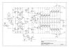
I did see the mistake on the 8008 schematic (pinout at servo), and corrected this accordingly if I'm correct (see my schematic). I'm unsure if it were the opamp I choose, or I simply just did a "****-up" in layout. I did fool around with the supply-voltage to the servo ect ect ect, but it always ended almost cutting one rail, making the other rail climb up, witch I've read is a sign of instability?What was going on with the DC servo? Did you copy the 8008 servo exactly? I ask because there's an error on the orig Aragon schematic.
The servo was OP37G and should be more the enough to work?
I've tried 1M instead of 2.2Mohm. Also 0.47 instead of the 0.1uf shown at the servo.
The power to the servo is taken from the known D3/D6 in Acurus.
I've tried lower the value before D3/6 from 22k to 10K accordingly as the 8008
Last edited: