• The move to the new server is done. There are some software and database maintenance updates in process. This has us passing the hat around to help out. We appreciate any donations. Seriously, even a dollar helps. The payment page may be found here - https://www.audiokarma.org/support.html

Acurus A250 and starground

Mondialfan, can you tell us more about your 40W class A Adcom 5400?
Not that long ago I stuffed more caps into a 5400. The 5400 has the advantage of separate front end and output stage rails, and with a CLC filter, I was able to make the front end extremely quiet:
https://www.diyaudio.com/community/threads/ps-hack-for-adcom-gfa-5400.361693/

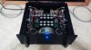
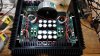
My 5400 based Class A is completely custom. I built the enclosure from a set of telecomm heatsinks, .375" cast billet front plate. I had the whole thing anodized black at a local shop. The folded cascode front end is fed from a pair of smaller toroids and CRC filtered front end supply boards. I'm using about 20V higher voltage to the front end, N. Pass told me to keep it at 12V or more due to high losses in the front end. The output stage is fed with a 1KVA Plitron. Each channel has its own power supply board and uses CRC filtering as well. The only thing taken from the 5400 was the channel boards. I used a set of custom output stage boards to better separate out the output mosfets and allow better heat dissipation. The output mosfets are all new and well matched for VGS.
20150419_151246.jpg Interior1_sml.jpg
 
Mondialfan, we've bumped into each other before over there at diyaudio in another Adcom thread or two, and I still have saved your schema for 5400 mods...
Cheers!

Twice the caps, half the ripple! Don't waste empty space in an amp!
 
@mondialfan I'm quite inspired to try this in my A250 if possible.

You can try it but there's not a lot of gain to be had on an A250 IMO. In a lot of class A amp's the amount of ripple on the main power supply caps can be quite high due to the high idle current requirements. A lot of that ripple can pass through from the power supply to the output stage in the form of nasty audible hum. Not to be confused with ground loop hum which is different but will sound the same. A good way to tame this ripple on the power supplies is to massively boost the capacitance, but also to split the capacitance into smaller series sections separated by an inductor or a low value high wattage resistance, say 0.15r, which will drop a lot of the mains ripple off of the second set of series caps after the resistor.

The reason I say that it will not produce much gain on an Acurus is due to the fact that the idle bias is quite low in an Acurus amp, so the ripple on the main supply caps is very small compared to a Class A amp which may have several amps being drawn from the main caps at idle. The residual noise of an Acurus is typically in the 100 - 200uV range, so noise while idling is almost nonexistent. I can typically put my ear up a foot or so from the speaker and there's no noise whatsoever on an Acurus amp. This is not the case with my Class A amps, there's usually some amount of hum present and this can usually be lowered quite a bit by building a CRC or CLC filter network.

Now you could make an argument that at higher power output levels the ripple will increase and yes it would, but how much of an effect it'll have on the sound is up to the listener.
 
@mondialfan I've been looking at D3/D6 in Acurus... I understand the purpose in Aragon, since they supply the ±12VDC to the servo if I'm correct.... But why are they in the Acurus? Protection or??

Best Regards
 
I’m also working on an Adcom Gfa5400 right now I guess I’m not the only one that is into old Acurus and Adcom amps! I was wondering if adding post fuse caps like we do on the Acurus amps would do any good on the Adcom Gfa5400.
 
@mondialfan I've been looking at D3/D6 in Acurus... I understand the purpose in Aragon, since they supply the ±12VDC to the servo if I'm correct.... But why are they in the Acurus? Protection or??

Best Regards

D3 & D6 are 12v zeners that set the reference voltage for the cascode transistors. This is a simple zener emitter follower circuit.
 
D3 & D6 are 12v zeners that set the reference voltage for the cascode transistors. This is a simple zener emitter follower circuit.
Sorry for my "simple" questions... In Denmark it's impossible to educate in low voltage electrics, they closed this line of education for reasons I do not know of regarding radio/amp study.. and evening courses is also non existing to my knowledge. So it's up hill for a new-commer who wants to learn besides from the knowledge on Google :(

Best regards
 
Sorry, I didn't intend to imply the solution or understanding of the regulator was simple. Sometimes my rushed responses on threads leave a few holes in what I meant to say.

This voltage regulator type is a simple one and they grow much more complex from there. Take a look at one of the old Walt Jung reg's or some of the other designs out there and you'll see they're almost as complex as the Acurus A250's entire circuit. However as you might expect the simple reg's do not control voltage as well as the highly complex reg's do, but a super low noise voltage reg is not always needed. In this case, in the front end of the amp the simple one with low parts count is sufficient.
 
Sorry, I didn't intend to imply the solution or understanding of the regulator was simple. Sometimes my rushed responses on threads leave a few holes in what I meant to say.

This voltage regulator type is a simple one and they grow much more complex from there. Take a look at one of the old Walt Jung reg's or some of the other designs out there and you'll see they're almost as complex as the Acurus A250's entire circuit. However as you might expect the simple reg's do not control voltage as well as the highly complex reg's do, but a super low noise voltage reg is not always needed. In this case, in the front end of the amp the simple one with low parts count is sufficient.
I've looked at several diff-sections (schematics) in many different amps, but didn't see the match Vs acurus.. your post might solve the misty:)
 
Happy Holidays! AudioKarma,

I own a non-working Acurus A250 that I hope to rebuild soon. After reading this entire thread multiple times, developing a plan to rebuild my amp, and annotating multiple circuit diagrams for the Acurus A250, I wanted to summarize some major recurring themes, and share them for reference by future owners/builders in the spirit of DIY. Whenever possible, I’ve listed the post number, or added a link. The schematics used as a reference are located here #19 #163 #774
I’ve also attached a tab-delimited TXT file (exported from Excel) listing these items and some preliminary pricing (sometimes using what’s in-stock today vs the best recommendations on this thread)
If I am missing or providing inaccurate information, please let me know so I can correct or post a new summary. Thanks to all who have shared, asked, or answered questions raised in this thread.

A) PSU mods
1) replace the two big Power Supply (Filter) capacitors, increase quantity from 2 to 4, 6, or 8; increase total uf from 46k uf, up to 100uf or more. Reduce ESR and Ripple Voltage as much as possible, triple-check size and proposed location of capacitors fits in the case securely. #54, #376 through #379, #547, #611, Cap Sizing at #204
2) Create a star-ground point at the center of a copper or aluminum plate or heavy-duty wire connecting 2 or more filter capacitors. See photos at #7, #382, and #608 through #611.
3) Provide bleeder resistors between each filter capacitor + and - leads. Optional - add bypass capacitors at the PSU, or post-fuse on the amp boards (see also note C5) for details. #9, #36
4)Replace rectifier with One (or Two rectifiers - Two allows for potential dual-mono style channel separation) Part # GBPC3506-E4/51, notes at #5 Photo at #7,
5) Add Turn-on delay/ softstart circuit to reduce inrush current, either via thermistor, or more complex custom inrush control circuit. #28 through #32; #376
6) Potentially add a CRC snubber between the transformer and rectifier(s) to reduce transformer ringing (can be calculated via Quasimodo jig from DIYAudio.com) See PDF link to document by Mark Johnson.

B) Rail conditioning
1) Add post-fuse parallel capacitor network on both rails per board to reduce noise/ripple from PSU. One 47 uf to 100 uf (100v) Plus 1 uf 250v ECWF in parallel, wired to board.. See posts #17, #18, #128 through #130 ;Photos at #177 through #180.

C) Capacitor Refresh on main circuit boards
1) Polypropylene Caps - #704 through #708
2) Late Production Change at C13, C14 from 39pf to 200pf, but in other comments on this thread, the recommendation is to use Mica caps at C12, C13, C14 – 220pf #106
3) Late Production change: Add 15 pf cap near Q4 & R18 - shown on reference schematic #19
4) Input coupling caps: C1 (.47 uf ECWF) and C2 (10 uf, 35v Nichicon Muse BP) #5
5) Nichicon Muse 220 uf, 50v at C7 ; #156
6) C16 Removed - shown on reference schematic #19
7) PSU Capacitors can be bypassed individually, (#159) though potentially, most of the benefits from this mod are already gained by adding the post-fuse capacitor network discussed at note B1. (#8 - #9, and #35 through #37)
8) Add bypass capacitors to Zener Diodes D3 and D6 for lower noise… #11 through #14.

D) Output Zobel Circuit
1) Relocate zobel network on Left-hand board away from thermal switch to reduce noise on left channel. #516
2) C15 was changed from .10 uf to .22uf in late production, - shown on reference schematic #19 see also resistor change at note G2.

E) Speaker terminal Ground
1) Disconnect ground wire running between Input RCA and Speaker terminals on each channel, run wire directly from Input RCA to Star-ground. #761 through #765
2) Diagram of Star Ground with above connection removed in red: #151
3) Add speaker protection board with DC detect; turn-on and turn-off thump protection. (Multiple diy or ready-built solutions available) #737 : #738; #790.

F) Switch replacement or repair
1) Repair #298, #594 through #599, #743, photo at #698
2) Replacement #643
3) Arc suppression caps #33

G) Board Resistor Refresh
1) General replacement recommendations #2
2) Late production change: R34 from 10r to 1.5r #322 use wirewound resistor, - shown on reference schematic #19 see also Zobel change at note D2.
3) R7 and R14 – increase to 1-watt. #141
4) Update Bias Potentiometer to 1K r multi-turn, measure value of existing Potentiometer and pre-set new to similar value prior to installing (somewhere in the middle?) Photo #41, #703

H) Transistor Replacement and Matching
1) Replacement tips and hints: #333, #482 through #510; #661 through #698
2) Matching Transistor PDF doc from DIY Audio Hafler DH200 Mod forum.

I) Bias checking and setting
1) How to check bias #280
2) Bias resistor / potentiometer – See note G4.
3) Bias recommendations 6-13Mv depending on rail voltage and speaker impedance: #69, #715
4) Bias and distortion #679

J) Powering-up after mods or repairs
1) Variac and Dim-Bulb tester - #57

 

Attachments

Last edited:
Some thoughts to the above:
-The bridge rectifier should be with spade connection instead og solderpins. Much easier to work with, and I regret I didn't do so in my first build.
-Regarding the star ground: keep the grounds as original if you cannot measure afterwards. Moving the RCA ground form SPK- to ground centerpoint in PSU is ok though, and is done in this way in the newer Acurus lineup by Mondial. Yours could be like this all ready??
-Best build without to much room for errors is the simple 2x36.000uf e.caps or the more experienced 4x20.000uf with dual bridge rectifier.
It took me a year building the 8x13.000uf version, and and awful lot of planing due to lack of space!
-I don't use softstart, but a SL32 2R025 does the job quite well to all the above e.caps I've listed.
-I haven't implanted a speaker protection, but it should be possible if there is space in the chassis and this could be powered from the main xformer secondary, or else I cannot see the fit.

Best regards
 
Last edited:
Thanks KNielsen! I could not find a comparable-spec rectifier to the VBE55-12NO7 with spade connections, do you have a part number I could look-up?
 
Mouser part#: 25-GBPC3506-E4 or similar

There are more fancy units out there that you might find more attractive, but 35A/600V will do the job. Used standard in both Acurus and Aragon.

The VBE55 and similar came with different terminals at the time, also screw terminals if I remember correctly. This might also be a solution, but more expensive
 
Back
Top Bottom