• The move to the new server is done. There are some software and database maintenance updates in process. This has us passing the hat around to help out. We appreciate any donations. Seriously, even a dollar helps. The payment page may be found here - https://www.audiokarma.org/support.html

Acurus A250 and starground

I do have one flow-up question, the 100r emitter resistor you mention, does it go between the two new 992/1845 emitters to be joined? or after they are soldered together - between Q4/Q8 and Q11/Q1. I don’t see this component on the A250 schematics I have.
Thanks again!
Six.
The resistors isn't included in the A250, as the emitter is shared and not possible. I've looked on the A250 pcb several times, and a mood for 10ohms in-between doesn't seem to fit, and some traces must be cut and rearranged to work.
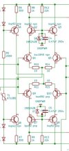
I've attached a schematic that shows the position of the resistors at Q4/5/9/10

Regards Screenshot_20211102-181712~2.jpg
 
  • Like
Reactions: Six
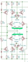
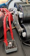
This is how it looks in A250... Remember that Q4/5 is one packed, as is Q9/10 in this example also... With only 5 legs (shared emitter) instead of 6-leg with each their own emitter as previous posted schematic.
 

Attachments

  • Screenshot_20211102-181712~3.jpg
    Screenshot_20211102-181712~3.jpg
    43.2 KB · Views: 11
  • Like
Reactions: Six
This is how it looks in A250... Remember that Q4/5 is one packed, as is Q9/10 in this example also... With only 5 legs (shared emitter) instead of 6-leg with each their own emitter as previous posted schematic.
Perfect, I can see how they should be placed, and it makes sense, the 100r resistors you mentioned on post 878 seem to have a similar function to the 10r de-generation emitter resistors that appear on the 2nd Gen A200 schematic shown above (should they be 100r? or 10r? or are they different enough applications that 10r works on the A200 while 100r is required for the A250? ) Thanks again for sharing the details graphically through schematics as well as verbally!
Six
 
Last edited:
Acurus uses 10ohm, Aragon is 100ohm, other uses even higher values.
I haven't measured the difference nor have the knowledge to elaborate what's best in your case. Between the two values I've only tried 100ohm for now in my own project. The A200 I owned I didn't experiment with the 10ohms, so I cannot tell if there is hidden gain to be made or not at this point.
I think the resistors forces some current sharing between the transistors even at lower ohm-values, without any further knowledge at this location.
@mondialfan knows for sure, and would be better to aske :)

That said, if you really want them in your A250 together with the 992/1845 without cutting the PCB, you'll likely have to bend each emitter leg and P2P solder the resistors. You might end up with some half good solutions to succeed, one of them might be to skip the good contact between the diffpairs in favour of the resistors in place.
I wouldn't do it.

Regards
 
Last edited:
@Sixto1 Google gave me this, I just copied some of the text and attached the link below:

"Emitter/source degeneration is a technique used to guard against drift in transistor parameters like beta. In addition, it helps linearize the small signal output"

and

"A degeneration results in a feedback system. As is customary in case of feedback systems, care should be taken to ensure that the system is stable (i.e., is in an oscillation-free regime including insufficient phase margins or satisfying Barkhausen criteria). The degeneration resistor should not pick up parasitics. Long traces on a PCB can induce stray inductance. Ground planes can add parasitic capacitance. If the degeneration resistor picks up parasitics like those mentioned above, then Re is no longer resistive but a complex impedance and will be reflected in the loop gain AB. In that case an additional phase shift will be added to the loop gain. If the phase shift is significant then the amplifier may move closer to the oscillation regime. "

 
  • Like
Reactions: Six
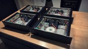
Four Acurus A250 amplifiers in for a restoration and some small fixes... No mods this time besides from the powercoard.
-Two of them comes with the standard AC-wire hanging out the back, this is changed to a AC connector like the newer models in both (a bit time-consuming, but nice when finished).
Also the powerswitch is rebild with new LED in all four while they are here. Only one of the three powerswitches is still working, so....

I think I've made six Acurus A250 for the same owner two years ago! They are all a part of a bigger home theater system! Massive power!!

I've tested all four with various curves up till 100kHz. All came out clean, so the project can continue.IMG20230911204657.jpgIMG20230911204454.jpg
 
  • Like
Reactions: Six
Did you relocate the power cord on the back panel to the center, or made a larger opening for the IEC receptacle in its current location? How about the fuse? Love to see a detail photo of how you routed the power on the inside, and how the finished IEC receptacle looks from the outside.

On my end, all the parts are here for the A250, but I've decided I need more hands-on experience before I dig into them. I'm currently doing some preliminary research and practice on a Hafler DH200. My current goal is to trace the PSU voltage and the audio signal, on a simpler circuit, and experience the impact of the various transistor stages on voltage and current. I'd also hope I will be able to spot where the noise/distortion comes from by using my oscilloscope and REW. It's a slow learning curve at my young age of 62, but I hope these efforts will reduce headaches later as I pursue this hobby.

I did take a look at EveryCircuit, its nice how it shows the current and voltages, and gives you a waveform, but I found it cumbersome for larger circuits, and does not seem to have an extensive parts library so I'm trying LTspice and Qspice also. I keep going back and forth between simulation and bread-boarding small circuits to see how they behave... still not making a lot of sense out of it all, though.

Thanks - Six.
 
Did you relocate the power cord on the back panel to the center, or made a larger opening for the IEC receptacle in its current location? How about the fuse? Love to see a detail photo of how you routed the power on the inside, and how the finished IEC receptacle looks from the outside.

On my end, all the parts are here for the A250, but I've decided I need more hands-on experience before I dig into them. I'm currently doing some preliminary research and practice on a Hafler DH200. My current goal is to trace the PSU voltage and the audio signal, on a simpler circuit, and experience the impact of the various transistor stages on voltage and current. I'd also hope I will be able to spot where the noise/distortion comes from by using my oscilloscope and REW. It's a slow learning curve at my young age of 62, but I hope these efforts will reduce headaches later as I pursue this hobby.

I did take a look at EveryCircuit, its nice how it shows the current and voltages, and gives you a waveform, but I found it cumbersome for larger circuits, and does not seem to have an extensive parts library so I'm trying LTspice and Qspice also. I keep going back and forth between simulation and bread-boarding small circuits to see how they behave... still not making a lot of sense out of it all, though.

Thanks - Six.
I'm on my way to bed, but just a quick answer:
I haven't started the process of cutting the holes for the IEC yet, but it will be placed where the original cord is mounted on the left side.

EveryCircuit is useful for "simple testing" but lack the power of real simulation where more proven values of transistors ect comes into play

Regards
 
On my end, all the parts are here for the A250, but I've decided I need more hands-on experience before I dig into them. I'm currently doing some preliminary research and practice on a Hafler DH200. My current goal is to trace the PSU voltage and the audio signal, on a simpler circuit, and experience the impact of the various transistor stages on voltage and current. I'd also hope I will be able to spot where the noise/distortion comes from by using my oscilloscope and REW. It's a slow learning curve at my young age of 62, but I hope these efforts will reduce headaches later as I pursue this hobby.
Nice. Depending on how far you wanna do the Acurus, it's quite straight forward within reason, and the PCB is one of the easier to work with due to the one layer layout.
Personally most of my flaws when I did my first Acurus came from overseeing tiny soldersplashes or microscopic bridges between solderpads on the PCB, so I would recommend some good checking of the PCB after soldering in a well lighted room and of course a DIM-bulp or a variable powersupply at first powerup.

Here I'm on a stall with my hobby, not enough time and my saggy English doesn't help me pushing my hobby forwards as in the beginning.. Trail and error in practice in my office seams a better option for me at the moment..
-So, I decided to try something different from Acurus-rebuilds and ordered a Wolverine EF3-4 poweramplifier PCB-set from a dedicated team at the DIYAudio forum. The build is described into minute details with what to be aware of, part selection, voltage targets, matching technique ect ect... Maby this will exchange the learning curve a bit further :)
I've got most parts for the build, and is filling the last basket from Mouser right now that will arrive around Dec2023 due to backorders. It's NOT a cheap amplifier to build, so I'll guess at least 5-6month before it's finished so I don't ruin the family economy while building and keep a happy wife :D

Best regards and good day
//K.Nielsen
 
Last edited:
Did you relocate the power cord on the back panel to the center, or made a larger opening for the IEC receptacle in its current location? How about the fuse? Love to see a detail photo of how you routed the power on the inside, and how the finished IEC receptacle looks from the outside.
If you do 8 e.caps in the PSU, then page1/post#1 and till page3/post#54 will show you how I did it.

I'll take some before/after IEC-pics when I do the amps that's in right now. Might do them in a week or so.

Also, if you wanna do your Acurus like the one I picture here, I have groundplates "in stock" and I can spare one..
It's 3mm thick steel, lazercutted. This will give you the psydo dual mono layout without having to move the AC inlet..
I can recommend Kemet ALS80 e.caps, also used in the shown amp here. The sound from the amp was absolutely one of the better :)
IMG_20200601_160742_621.jpg
IMG_20200601_135110.jpg
 
Last edited:
Thanks K!, I think I have the filter caps solved, I went with 4 ALS70A203KF100 for each of my 2 amps, but I’m separating positive, negative and ground for each channel and using a ground-lift between each channel and the single chassis-earth connection. I’m keeping the stock power cord for now, might upgrade to IEC later. I’m using aluminum angles and bar to get the connection geometry similar to your laser cut plates (kind of a trapezoid shape) and I’m thinking of building a small wood shape to hold the back-end of the caps and keep the whole thing from shifting around.
Sounds like we both have some fun work ahead of us, looking forward to continuing the journey and following your progress!
Six.
 
Four poweramplifiers done.
Only restoration with new caps and some resistors. All powerswitches were fixed with new LED and harnes to go...
For two of the amps an IEC were installed and went perfectly without any trouble.
Among other small issues the signal-wire where in two of the amp-modules badly corroded near the connection to the circuit and needed some TLC and resoldering.
Five new fuseclips were also needed, 2 bleeder resistors were missing and some new screws in between here and there.
-As good as "close to" new again, all measure well up till 100kHz, DC-offset remain below 7mV for all four units.
IMG20230924210033.jpg

Best regards
 
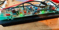
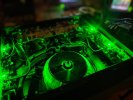
Just playing around with my A250...
I've installed green diodes at the CCS as these should be less noisy then 1N4148 according to some measurements on DIYAudio.
The diodes have a forward voltage of 2.65V and 2mA IC, this makes the 200Kohm that's already installed usable, and doesn't need adjustment. There should be approx 790μA across each diode with the 200Kohm, so all good.
I've altered the 300ohm to 768ohm witch should settle the current to somewhat usable value afterwards...
I aim for roughly 2.3-2.4mA pr CCS.

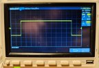
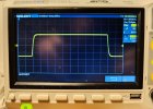
At the TTA/TTC predriver I've removed one of the 82ohm pr side and replaced with a 150ohm witch gives a parallel 53ohm afterwards. I would have tested a colder operation anyway, so might just do it now while "playing with diodes" and see what the squarewaves looks like:)

As it's all in TEST STAGE I can't report the final outcome yet with mA/temperature/ect.... I did one test last evening at 230VAC and found my first proto CSS with other values then written here to agressive; forcing +12mA in the predrivers! They didn't cook, but temp at around +50°C was to much I think.
Tests were performed anyway up till 50kHz and the squares were good.
The total output did however suffer badly with only 280watts@8ohm one channel driven!! Auchhh.... I didn't probe around as it became clear that the CCS was set above the abilitys of the A250;)

I'll type some measurements later after mentioned adjustments.

Best regards
IMG20231030161517~2.jpg
 
Last edited:
First test today (full railvoltage):
CCS: 2.34mA pr rail.
Pre-driver: 9.56mA measured across the 53ohm.

1kHz and 10kHz shown. BIAS is roughly 5-6mV and a semi cold amplifier.
IMG20231030211407~2.jpgIMG20231030211443~2.jpg

Normally there will be a small minute overshoot on squarewaves with the TTA/TTC-pre's installed. This is almost completely eliminated. Quite happy with the curves:)

The amplifier don't measure above 300w at 8ohm one channel driven. Rails are 82.7VDC and I'd get 298watt before clipping... I did 349watts at 92VDC in the start of this thread with this amplifier, so the numbers seams right..

Regards
 
Last edited:
It's definitely not always I clap in my hands after some "mods" and listen to the work performed... This time I clap!
I really regret that I cannot perform noise measurements and so forth to see some data Vs sound... But these few adjustments have made a more relaxed amplifier for sure all though I didn't do 2.4mV CCS witch would be optimal (lack of right resistor's). I have a full mooded Aragon 4004 next to my A250, and besides form the lag of bass-power, the A250 really does sound nice :)
 
Last edited:
Took the plunge and did a much needed rework on my poweramplifier today.

INPUTSTAGE:
The DC-offset had started to drift the last two years or so, from approx 5mV when I built the thing to around 20mV meassured this morning, also there was some crackling sounds from the tweeter now and then, so I suspected for a long time that the 2SA798/2SC1583 diff-pair had done their job and needed a replacement.
I matched a set of KSA992F/KSC1845F to the mV on the Vbe, and used my "Chinese Mega328" to get an slight view of matching Hfe between the pairs.
I installed the new diff-pairs back-to-back with a dap of superglue and heat shrink.
The crackling noisy sound is gone and DC-offset is stable at 2mV... All good...

OUTPUT-STAGE:
Next up was the power transistors.
Measuring across the emitter resistors the old Toshiba's didn't perform that good anymore. Worst case one of the 2SA1302 measured 6mV at the emitter while it's freind sitting right next to it on same rail measured 13mV!!
Since the amp doesn't have speaker protection I didn't dear wait till one of the outputs would reveal it's magic smoke, so new quad matched pairs of MJL1302/MJL3281 were installed afterwards. I'm quite impressed by the tight tolerences from On-semi's MJL-series. I only matched Vbe on each device while mounted on a decent heatsink (I didn't check Hfe), but the result is within 0.1-0.2mV across each emitter now! Very impressed:)

CURRENT SOURCES:
The CCS were also altered a bit for a better performance to the overall typology then my first LED-diode conversion at post#894 where the current was a bit to high. I had tried different resistors after the post above, without really getting the target right...
Today I swapped in another type of LED and adjusted current accordingly. Checked the current at the pre-drivers and drivers and double checked again after the amp had heated up. Much better then before the rework..
It's the same LED's that I use in my preamp and RIAA and the specs seams to be far better within the same batch then the LED's I used in previous post in this amplifier. The LED's are 2mA-type and set to 1.5mA for a longer lifespan.

RESULT:
One thing I really like is a decent drop in heatsink temperature without hotspots like before. Not getting ahead of myself I set the BIAS to 8mV and kept things with in reason this time.
A bit unexpected the watts claimed from 310w@8ohm before the work performed to 325w@8ohm.. Not a big jump, but still an unexpected increase with rails below 85Vdc:)
The amp sounds healthy, and pulling the 2SA798/2SC1531 and adjusting the CCS was the right decision.

Edit: a sidenote: to get some of the readings especially at the driver stage I did turn off the amplifier to move my probes in position and then turn on the amp again for meassurments. Space is tight when the amp is put together and making undesirable shorts is quite easy

Good day folks // Regards
1000004012_20240411192006104.jpg
 
Last edited:
Working an a A200 this weekend.
I completely forgot the feel of quality on these output stages. Looking at the layout, solderpads, coppertraces ect it's just so much better done from factory then the A250 ever was. So satisfying:)
 
Only one mistake found on the A200 PCB's:
C17: the unpopulated "post-fuse-cap" footprint on the PCB isn't connected after the fuse, but before the fuse. The opposite C16 is OK.
Since I'm gonna use these spots for Panasonic ECWF(a) 0.47uf I made a cut in the coppertrace between C17 and the positive connection and made a small jumper so C17 is now connected after the fuse on the positive side as supposed to, or so I believe.
C16/17 now have equal resistance to the PSU and can both do their wonders directly on the rails... Might be overkill!?!!

IMG20240413164853~2.jpg

Also: There is a "C4" that isn't populated, and doesn't show on the schematic either. Adding a cap here (normally a 0.1uf) would act in parallel with the 10ohm/antiparallel diodes at the input ground. Since non of the Acurus amps that I've worked with uses a cap here I'll leave it unpopulated.
 
Last edited:
One thing: I searched Google for rail voltage on the A200 as I got a bit confused at first powerup when the A200 arrived. I thought the rails would be ±70VDC up till ±75VDC??
For some reason I haven't noted the rails on the A200 I once owned myself.

The one in my bench measured ±83.7VDC when testing the unit before ordering parts. The original PSU e.caps is rated at 85VDC!!!! Really no headroom at all!

There is no voltage selector, the amp is just marked with a 230VAC sticker from factory, witch is the correct voltage for European use.

I meassured both channels individually with different curves, all good, and both channels did 316watts@8ohm before clipping, so within A250-territory.

The transformer still looks like 800VA, a 2-channel load test would confirm this..
 
Last edited:
Back
Top Bottom