• The move to the new server is done. There are some software and database maintenance updates in process. This has us passing the hat around to help out. We appreciate any donations. Seriously, even a dollar helps. The payment page may be found here - https://www.audiokarma.org/support.html

Acurus A250 and starground

D6 is the voltage reference for the cascode which protects the input diff pair Q11 from full rail voltage. The 2SA798 is only rated for 50V Vceo. If D6 were beginning to fail open then that would allow the voltage to drift up from the 12V rating of the zener to as high as the full rail voltage. If the voltage as measured at the bases of Q9/10 were to go up well above 50v then damage to Q11 can be the result. Q9/10 would be okay as long as the current through them did not become excessive.

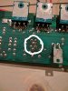
I would definitely be looking closely at the rear of the board in the general area of R14. There are several connections there that are very close and some are connected and others are not. I always highly scrutinize this area when I'm performing upgrade work, its the one area that would be easy to get a solder bridge in the wrong spot.
 
D6 is the voltage reference for the cascode which protects the input diff pair Q11 from full rail voltage. The 2SA798 is only rated for 50V Vceo. If D6 were beginning to fail open then that would allow the voltage to drift up from the 12V rating of the zener to as high as the full rail voltage. If the voltage as measured at the bases of Q9/10 were to go up well above 50v then damage to Q11 can be the result. Q9/10 would be okay as long as the current through them did not become excessive.

I would definitely be looking closely at the rear of the board in the general area of R14. There are several connections there that are very close and some are connected and others are not. I always highly scrutinize this area when I'm performing upgrade work, its the one area that would be easy to get a solder bridge in the wrong spot.
Yes.. this is the area where thinks can go wrong, and indeed hard to find if the new soldering is making "new" connections.
The amp did sound as it should even though the bass behaved different, so I'll hope to spot a leak on the board. I do have parts to restore the hole board including the diff-pair.. But as these are impossible to find (originals, not Chinese copies!) I'm hoping NOT to change theses :)
 
If the voltage as measured at the bases of Q9/10 were to go up well above 50v then damage to Q11 can be the result. Q9/10 would be okay as long as the current through them did not become excessive.
I'll guess the voltage is measured between powerground at the board and base of the transistor?
Just in case...
 
Checked, double checked... Annnnnd checked again.
Everything measure correct now. Inspected the board with sharp light from the table pointing towards the board while holding a magnifying glass looking at the soldering and the circuit itself on the other side.
Putting this together one more time, hope this will be the last time :)

Regards
 
Victory!!!! So fare everything is good :) :)
1.9mVdc at speakerterminal. No blown light bulb ;)
I haven't got more time, here it's 11:30pm, so a listening session and BIAS readjust will be tomorrow after work

Stay tuned :beerchug:IMG_20191006_231923.jpg
 
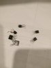
FIY... I changed the diff pair and the transistors related together with D6

The old diffpair on the pic measure:
Q4: 386/425hFE
Q11: 383/525hFE

They aren't dead but I felt especially Q11 should have done better, so changed them.
IMG_20191006_232726.jpg
 
Last edited:
It's goooood...!
After removing the bulp from AC, the DC at the terminals went further down to 1.2mVdc, quite OK..
It sound as it should, an most important the left speaker is now under control again :)
 
Great news I’m glad you got it fixed! Was this your personal amp?
For a freind. Full restoration.
I don't know if the bad connection at C7 has coursed all this trouble. Funny thing is that non of the transistors were really dead.. All related transistors to the diff-pair were ok, but the diff itself didn't really measure that good.. The amp had been playing for a couple of days without I noticed the "odd" behaviour of the bass speaker. Even though I do spend a lot of time listening to the amp projects....
Anyhow, when I swapped new transistors, D6 was also measuring correct again! I pulled three D6-diodes before changing the transistors. But I do not understand this........
This amp has been to a radiomechanic two times before me, so maby(????), the fault has been there the hole time, you couldn't hear the lack of control in the low end frequency anyway.... Odds are that non of radio-dudes had a new diff-pair, I just used those I had.. :eek:
I never plug an amplifiers that I receive to my private speakers before I'm finished and confident that it'll work. But this one cheated, playing good ---but lack of control. Untill now :)
 
Last edited:
I did some minor repairs on My T+A Criterion TAL140 speakers this weekend to seal a minor air leak that was causing some noise on bass heavy tracks and I was using my two channel Acurus 200x3 to really push the speakers hard to make sure I fixed the problem and I was very impressed just how powerful this amp is!
 
Last edited:
I was so happy with the mods I did on the two channels of my 200x3 I decided to go ahead and do the same on the third spare channel just in case I ever need to use it. Unfortunately the third channel has some issues, stupidly I didn’t thoroughly tested it when a I got the amp I just made sure DC offset was ok and it played music which it did. I connected it up the the power supply to test it after the mods and it won’t bias up, I get 0v across all emitters but the outputs test ok. I’ll likely have to wait til the weekend to investigate further. Just thought maybe you guys had an idea what could be wrong? On the positive the 2 channel 200x3 sounds amazing driving my big T+A floorstanders! The bass is incredible! These are the speakers I’m driving with the Acurus https://www.ta-hifi.de/wp-content/uploads/criterion_tal_140_en.pdf
 
I was so happy with the mods I did on the two channels of my 200x3 I decided to go ahead and do the same on the third spare channel just in case I ever need to use it. Unfortunately the third channel has some issues, stupidly I didn’t thoroughly tested it when a I got the amp I just made sure DC offset was ok and it played music which it did. I connected it up the the power supply to test it after the mods and it won’t bias up, I get 0v across all emitters but the outputs test ok. I’ll likely have to wait til the weekend to investigate further. Just thought maybe you guys had an idea what could be wrong? On the positive the 2 channel 200x3 sounds amazing driving my big T+A floorstanders! The bass is incredible! These are the speakers I’m driving with the Acurus https://www.ta-hifi.de/wp-content/uploads/criterion_tal_140_en.pdf
I tried the same thing, and actually panicked at first!!! :)
If you have changed to new multiturn pots, then give it some extra on the screw (anticlockwise for BIAS up, in my case many turns was needed), or try it anyway ;) It should start to show some mV on the meter......

Even at zero BIAS you can read the DC offset.
 
I didn’t install new bias pots the stock ones in my amp are nice quality Bourns parts that I’ve actually used as an upgrade in some Adcom amps I’ve rebuilt. Thankfully all the output transistors test good and Q15 is testing bad which I think would explain the bias problem since q15 is part of the bias circuit. Unfortunately I do not have any 2sc1567s in my parts bin but I do have a bunch of 2sd600k which seems to be almost an exact match. I can at least use the 2SD600k to make sure that’s the problem and if it is I can try and track down a 2sc1567.
 
The other two channels on the other hand are sounding amazing cranking out some classic rock on the big T+A speaker! The power switch light has started flickering though so I’ll have to fix that eventually
 
Maby a stupid question but, when I look at the A200 schematic, I do not see pin4(substrate)?? Is it tied with the 10ohms resistors?
I tried to Google the function of this pin, but think this is yet out of my league to understand with the examples I've managed to find :)

Thanks
 
Well... long time since I've been posting, much to do!!. But....

This one fights back.... An A250 for restoration, blows fuses... The owner bought it cheap and hope it will come to life again.
It's been soldered by previous owner, changing multiple transistors. The pic shows the work performed. Way to much heat has been used!
IMG_20191117_165909.jpg
This is definitely not an easy job since there is no system in the transistors that's been replaced by previous owner.. Q13/14 has been changed on both circuits and also Q8/Q9/10/12 on the one pictured.. Also Q4 doesn't look original, I hope it's not the case.

Regards
 
Last edited:
The owner describe:
"Applied new fuses to the circuits, applied power and listened to music.. When applying volume the fuses blew on both channels."

- I'm waiting for parts before testing can continue..
So far, the PSU measure correct, no transistors or diodes are faulty, all resistors are in good condition and even though some copper traces are "burned" by bad soldering, all signals passes without problems. One thing though: there hasn't been added thermal grease to the power transistors (so they are attached directly to the original paper-mica) after several repairs, only the old "completely dead" isolation is what there is left to separate the transistors form the heatsink. I don't know yet if this is actually the problem......... To be continued
 
Last edited:
Do you guys happen to know of a suitable replacement power switch? Mine is flickering to the point that it’s rarely actually on anymore.
 
Back
Top Bottom